
Jet flow division valve control method and flow division valve control double-jet-pipe electro-hydraulic servo valve

A diverter valve and dual jet technology, applied in servo motor components, valve details, multi-port valves, etc., can solve the problems of difficult welding of feedback rod components, easy to be affected by environmental vibration, and long rigidity of the jet pressure pipe. It is not easy to be affected by environmental vibration, the processing difficulty is not high, and the dynamic response is fast.

Pending Publication Date: 2020-02-28
JIUJIANG UNIVERSITY
View PDF0 Cites 1 Cited by
  • Summary
  • Abstract
  • Description
  • Claims
  • Application Information

AI Technical Summary

Problems solved by technology

The typical structure of the jet tube electro-hydraulic servo valve is a force feedback two-stage jet tube electro-hydraulic servo valve. This swinging single nozzle structure results in a longer jet pressure tube with low rigidity, which is easily affected by environmental vibration; the inertia of the moving parts is large. , slow dynamic response; the difficulty of welding and processing the feedback rod assembly and other defects are the difficulties that are difficult to solve in the current development of jet pipe valves

Method used


Image

  • Jet flow division valve control method and flow division valve control double-jet-pipe electro-hydraulic servo valve
  • Jet flow division valve control method and flow division valve control double-jet-pipe electro-hydraulic servo valve
  • Jet flow division valve control method and flow division valve control double-jet-pipe electro-hydraulic servo valve

Examples


Embodiment

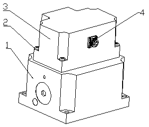
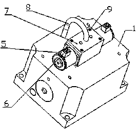
[0036] Embodiment: the main valve body 1 and the valve housing 23 in the present invention are made of high-quality steel 30#; the main valve core 16, the double cone valve core 26, and the splitter ring 25 are all made of 40Cr; the valve sleeve valve cover 3 and the end cover 12 , and the retaining ring 14 are made of carbon steel ZG25; the valve sleeve 15 is made of polytetrafluoroethylene; the model of the proportional electromagnet 5 is GP516-S-A; the seal material is made of NBR NBR; the return spring 13 is made of 70 steel. The processing of the main valve body 1 and the valve housing 23 is mainly completed on a CNC milling machine; the main valve core 16, the double cone valve core 26, and the splitter ring 25 are mainly completed by a CNC lathe.

[0037] When the control valve 7 is installed, first align the upper split ring 255 and the lower split ring 256 on the double cone valve core axis 262, and then use the screws 254 to fix the upper split ring 255 and the lower ...


PUM


Abstract

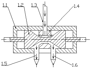
The invention discloses a jet flow division valve control method and a flow division valve control double-jet-pipe electro-hydraulic servo valve. Jet flow passes through a flow division splitting ringarranged in the middle of a shell of a flow division valve body through an impulse line and is sprayed out through spray nozzles at the top ends of jet pipes on the left side and the right side on the lower side of the valve body, so that jet divided output of the double jet pipes is achieved. An oil return opening is formed in the middle of a groove on the main valve body. A valve deck with a wiring terminal is arranged outside the control valve. The valve deck is connected with the main valve body through a screw. The size of an annular gap of double cones is controlled through a double-cone valve element, so that control over oil pressure and flow is achieved. The flow division valve control double-jet-pipe electro-hydraulic servo valve has the advantages that the impulse line is shortand high in rigidity and not prone to being influenced by environment vibration; the inertia of motion components is small, and dynamic response is rapid; a feedback spring rod is low in machining difficulty and easy to install; the anti-contamination performance is good, and the reliability is high. The flow division valve control double-jet-pipe electro-hydraulic servo valve provides a novel high-reliability key servo element for the Chinese national defense and the air transport industry.

Description

technical field [0001] The invention relates to hydraulic accessory technology, in particular to a jet flow diversion valve control method and a diversion valve control double-jet tube electro-hydraulic servo valve. Background technique [0002] The jet tube electro-hydraulic servo valve is the core component of the electro-hydraulic servo control system, which is widely used in ships, aviation, aerospace and various industrial applications. The typical structure of the jet tube electro-hydraulic servo valve is a force feedback two-stage jet tube electro-hydraulic servo valve. This swinging single nozzle structure results in a longer jet pressure tube with low rigidity, which is easily affected by environmental vibration; the inertia of the moving parts is large. , Slow dynamic response; the difficulty of welding and processing the feedback rod assembly and other defects are the difficulties that are difficult to solve in the development of the current jet pipe valve. Cont...

Claims


Application Information

Patent Timeline
Patent Type & Authority Applications(China)
IPC IPC(8): F16K11/07F16K27/04F16K31/06F15B13/02F15B21/08
CPCF16K11/0708F16K27/041F16K31/061F16K31/0675F15B13/022F15B21/087
Inventor 胡云堂邹晓燕王英惠江卓达林伟明訚耀保
Owner JIUJIANG UNIVERSITY
Learn More