


Quick Research
Generate reliable direction feasibility study reports for your R&D in just a few steps.

Technical Q&A
Discover and master advanced knowledge NOW. Basics, ideas, possibilities, all at once.

Find Solutions
As an expert in R&D theories, this can generate solutions to your technical problems instantly.

Evaluate Feasibility
Analyze your overall solution with one click, know your potential R&D risks in advance.

Monitor Landscape
Get weekly tech updates, stay abreast of the latest tech innovations and key insights.
Interlayer crane
A crane and hook technology, applied in the field of interlayer cranes, can solve the problems of complicated fine-tuning operation, high fine-tuning cost, inability to fine-tune the curtain wall skeleton, etc. Effect
- Summary
- Abstract
- Description
- Claims
- Application Information
AI Technical Summary
Problems solved by technology
Method used
Image

Examples
Embodiment 1
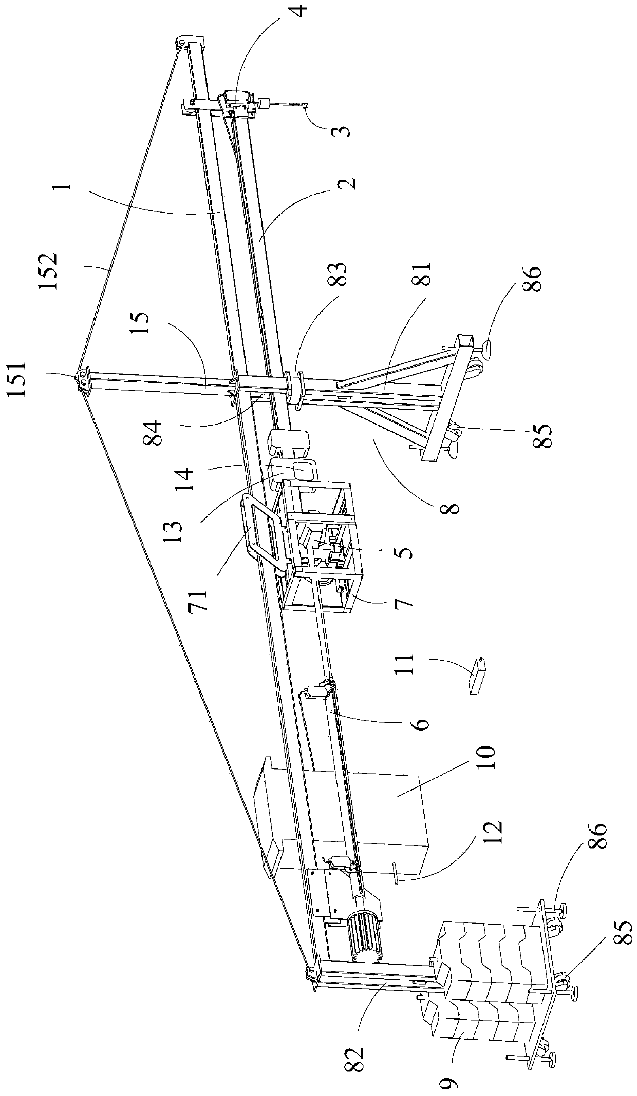
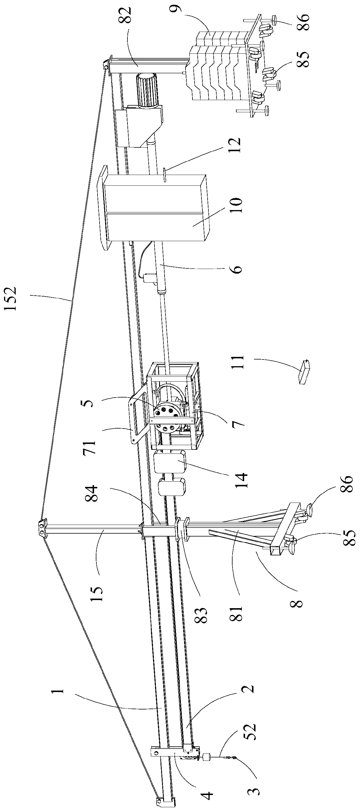
[0102] Such as figure 1 and 2 As shown, a kind of interlayer crane according to the present invention includes:
[0103] A fixed boom 1 arranged horizontally;
[0104] The mobile boom 2 is a rigid structural member;
[0105] The electric push rod 6 is connected with the movable arm frame 2 and the fixed arm frame 1 respectively, and the electric push rod 6 drives the movable arm frame 2 to reciprocate along the length direction of the fixed arm frame 1;
[0106] The reversing assembly 4 is used for reversing the hoisting wire rope 52 and is arranged at the front end of the mobile jib 2;
[0107] The hook assembly 3 is used to connect the suspended object and is arranged below the reversing assembly 4;
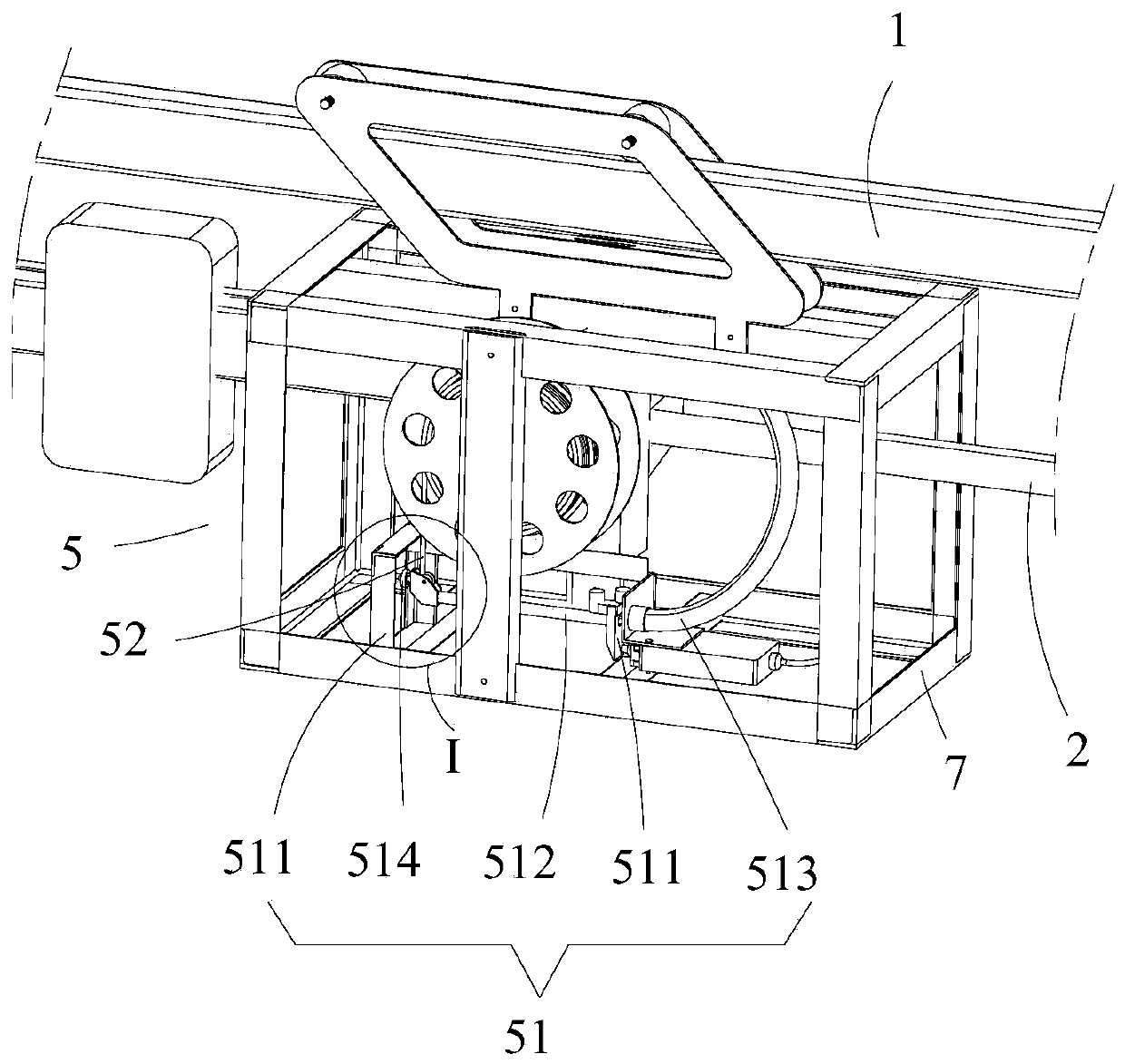
[0108] The hoisting mechanism 5 is arranged at the rear end of the mobile boom 2, and the hoisting wire rope 52 on the hoisting mechanism 5 is connected to the hook assembly 3 after being changed direction by the reversing assembly 4 , the lifting mechanism 5 drives the li...
Embodiment 2
[0122] Such as figure 1 and 2 As shown, a kind of interstory crane as described in Embodiment 1 is different from Embodiment 1 in that the bracket 8 used to support the fixed arm frame 1, the bracket 8 and the fixed arm frame 1 detachably connected, the bracket 8 comprises,
[0123] The vertically arranged front bracket 81 is detachably connected to the middle part of the fixed arm frame 1;
[0124] The vertically arranged rear bracket 82 is detachably connected to the rear end of the fixed arm frame 1 and is spaced apart from the front bracket 81 .
[0125] The fixed arm frame 1 is supported by the front bracket 81 and the rear bracket 82 arranged at vertical intervals. Compared with the single-supported crane, the wireless control crane support between the layers of the present application is more stable. At the same time, the front bracket 81 and the rear bracket 82 are detachably connected with the fixed arm frame 1 to facilitate the installation of the bracket 8. At t...
Embodiment 3
[0136] Such as figure 1 and 2 As shown, a kind of interstory crane as described in Embodiment 1 or 2, the difference between this embodiment and Embodiment 1 or 2 is that the fixed arm frame 1 is provided with a vertically arranged support rod 15 , the top of the support rod 15 is provided with a vertically arranged rope pulley 151, and a stay rope 152 is placed on the rope pulley 151. The stay rope 152, the two ends of the stay rope 152 are respectively fixed with the Both ends of the boom 1 are connected.
[0137] The part of the fixed arm frame 1 described in the present application that stretches out from the front bracket 81 is the cantilever end, which bears the downward gravity of the suspended object, and the front and rear ends of the fixed arm frame 1 are connected by a stay rope 152. The rear end applies an oblique upward pulling force to the front end of the fixed arm frame 1, and the vertical upward component of the pulling force can offset at least a part of th...
PUM
 Abstract
Description
Claims
Application Information
 - R&D Engineer
- R&D Manager
- IP Professional
- Industry Leading Data Capabilities
- Powerful AI technology
- Patent DNA Extraction
Browse by: Latest US Patents, China's latest patents, Technical Efficacy Thesaurus, Application Domain, Technology Topic, Popular Technical Reports.
© 2024 PatSnap. All rights reserved.Legal|Privacy policy|Modern Slavery Act Transparency Statement|Sitemap|About US| Contact US: help@patsnap.com