Eureka AIR delivers breakthrough ideas for toughest innovation challenges, trusted by R&D personnel around the world.

Welded pipe optical fiber laser flying sawing machine

A fiber laser and flying saw machine technology, applied in the field of flying saw machines, can solve the problems of increased production costs, noise pollution, irregular replacement costs, etc., and achieve the effect of reducing cutting loss and cutting noise

Pending Publication Date: 2020-02-28
SHENYANG CONTOR MACHINE & ELECTRIC EQUIP
View PDF0 Cites 0 Cited by
  • Summary
  • Abstract
  • Description
  • Claims
  • Application Information

AI Technical Summary

Problems solved by technology

[0003] However, in the existing flying saw machines, there are problems of large cutting loss and high cutting noise.
The online fixed-to-length flying saws on the welded pipe production line are all cut with saw blades. The cutting loss of the saw blade is large, and it needs to be replaced irregularly and the cost is high. When cutting stainless steel, high-strength steel and other materials, the requirements for the saw blade are higher and the loss is greater. , which directly leads to an increase in production costs; and the noise generated by the saw blade cutting is large, which is easy to cause noise pollution

Method used


Image

  • Welded pipe optical fiber laser flying sawing machine
  • Welded pipe optical fiber laser flying sawing machine
  • Welded pipe optical fiber laser flying sawing machine

Examples


Embodiment Construction

[0017] The following will clearly and completely describe the technical solutions in the embodiments of the present invention with reference to the accompanying drawings in the embodiments of the present invention. Obviously, the described embodiments are only some, not all, embodiments of the present invention. Based on the embodiments of the present invention, all other embodiments obtained by persons of ordinary skill in the art without making creative efforts belong to the protection scope of the present invention.

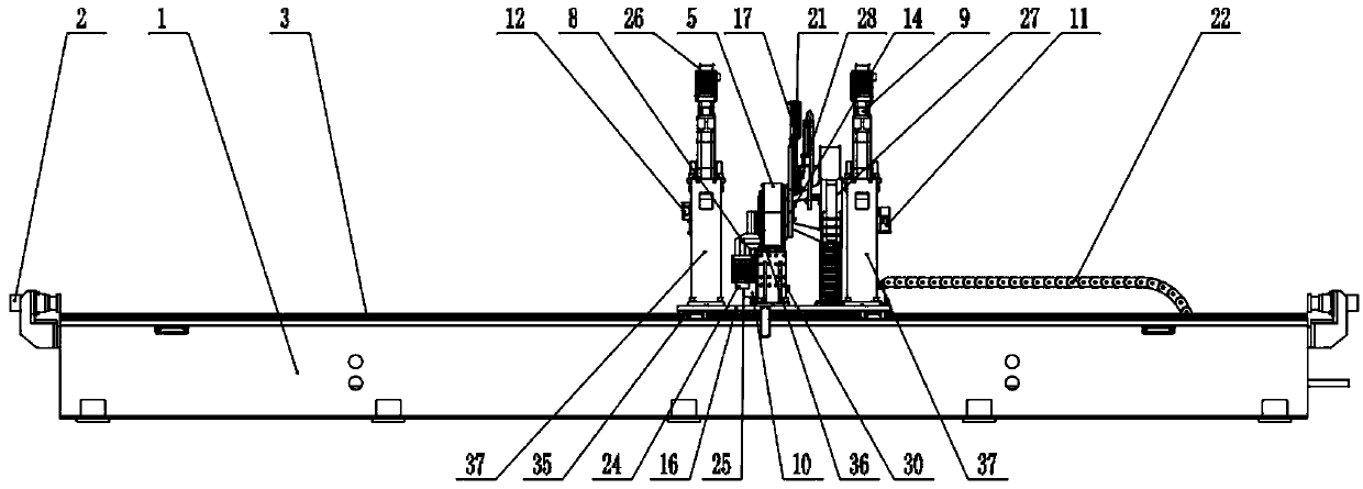
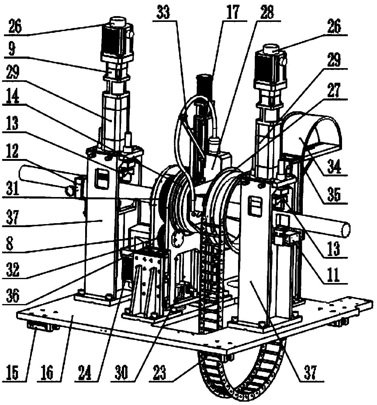
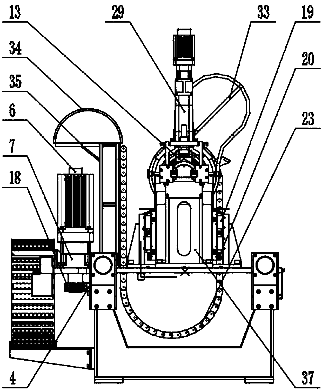
[0018] see Figure 1-4, the present invention provides a technical solution: a welded pipe fiber laser flying saw machine, including a flying saw bed 1, a liquid-gas buffer 2, a horizontal linear guide rail 3, a rack 4, a protective cover 5, a drag motor 6, a drag Reducer 7, rotation reducer 8, clamping reducer 9, lifting reducer 10, discharge guide cylinder 11, feed guide roller 12, clamping mechanism 13, rotation mechanism 14, first slider 15, trolley platfo...


PUM


Abstract

The invention discloses a welded pipe optical fiber laser flying sawing machine. The welded pipe optical fiber laser flying sawing machine comprises a flying sawing machine body, liquid gas buffers, ahorizontal linear guide rail, a rack, a protective cover, a drag motor, a drag speed reducer, a rotating speed reducer, a clamping speed reducer, a lifting speed reducer, a discharging guide cylinder, a feeding guide roller, a clamping mechanism, a rotating mechanism, a first sliding block, a trolley platform, a linear module, a first gear, a second sliding block, a lifting guide rail, a feedingmotor, a first drag chain, a second drag chain, a rotating motor, a lifting motor, a clamping motor, a drag chain disc, an optical fiber laser cutting head, an electric cylinder, an elevator, a secondgear, a third gear, an optical fiber support, an optical fiber guide groove, a drag chain support, a rotating support and a clamping support. The liquid gas buffers are correspondingly arranged on two sides of the flying sawing machine body. The horizontal linear guide rail is arranged at the top of the flying sawing machine body. The welded pipe optical fiber laser flying sawing machine has thecharacteristics of being small in cutting loss and cutting noise.

Description

technical field [0001] The invention relates to the technical field of flying saw machines, in particular to a welding pipe optical fiber laser flying saw machine. Background technique [0002] Flying saw machine is an automatic equipment for cutting continuous moving steel to length. It is widely used in the production line of high-frequency longitudinal welded pipe or section steel. It can realize automatic tracking sawing and flying saw under the high-speed movement of welded pipe or section steel. The welding machine is the production equipment of the last process on the welded pipe production line. [0003] However, in the existing flying saw machine, there are problems of large cutting loss and high cutting noise. The online fixed-to-length flying saws on the welded pipe production line are all cut with saw blades. The cutting loss of the saw blade is large, and it needs to be replaced irregularly and the cost is high. When cutting stainless steel, high-strength steel...

Claims


Application Information

Patent Timeline
IPC IPC(8): B23K26/38B23K26/08B23K26/70
CPCB23K26/0884B23K26/38B23K26/702
Inventor 李鹏
Owner SHENYANG CONTOR MACHINE & ELECTRIC EQUIP
Why Eureka
Eureka Blog
Learn More