
Full-automatic glass laser melting marking equipment and working method thereof

A glass laser and marking equipment technology, applied in laser welding equipment, welding equipment, metal processing equipment, etc., can solve the problems of heavy load of three-axis motion mechanism, easy damage of laser generator, poor traceability of glass products, etc.

Pending Publication Date: 2020-02-28
浙江愚工智能设备有限公司
View PDF1 Cites 2 Cited by
  • Summary
  • Abstract
  • Description
  • Claims
  • Application Information

AI Technical Summary

Problems solved by technology

The traditional method is to use a label to paste on the glass surface, but the label will be washed off during the glass processing process, resulting in poor traceability of glass products
[0003] Therefore, automatic equipment for laser melting processing barcodes, two-dimensional codes and other traceable marking processing on the glass surface has emerged. For example, a Chinese patent with the authorized announcement number CN207914781U discloses a glass plate laser coding machine, although the equipment The identification code is processed on the glass plate, but the laser generator in the laser coding component of the equipment is installed on the three-axis motion mechanism. On the one hand, the three-axis motion mechanism drives the laser generator to move. The laser generator vibrates, the laser generator is easily damaged, and the work is unstable; on the other hand, the heavy laser generator is installed on the three-axis motion mechanism, which causes the three-axis motion mechanism to bear too much weight, increases the difficulty of equipment structure design, and is prone to failure

Method used


Image

  • Full-automatic glass laser melting marking equipment and working method thereof
  • Full-automatic glass laser melting marking equipment and working method thereof
  • Full-automatic glass laser melting marking equipment and working method thereof

Examples


Embodiment Construction

[0074]The present invention will be further described in detail below in conjunction with the accompanying drawings and examples. The following examples are explanations of the present invention and the present invention is not limited to the following examples.

[0075] Example.

[0076] see Figure 1 to Figure 17 .

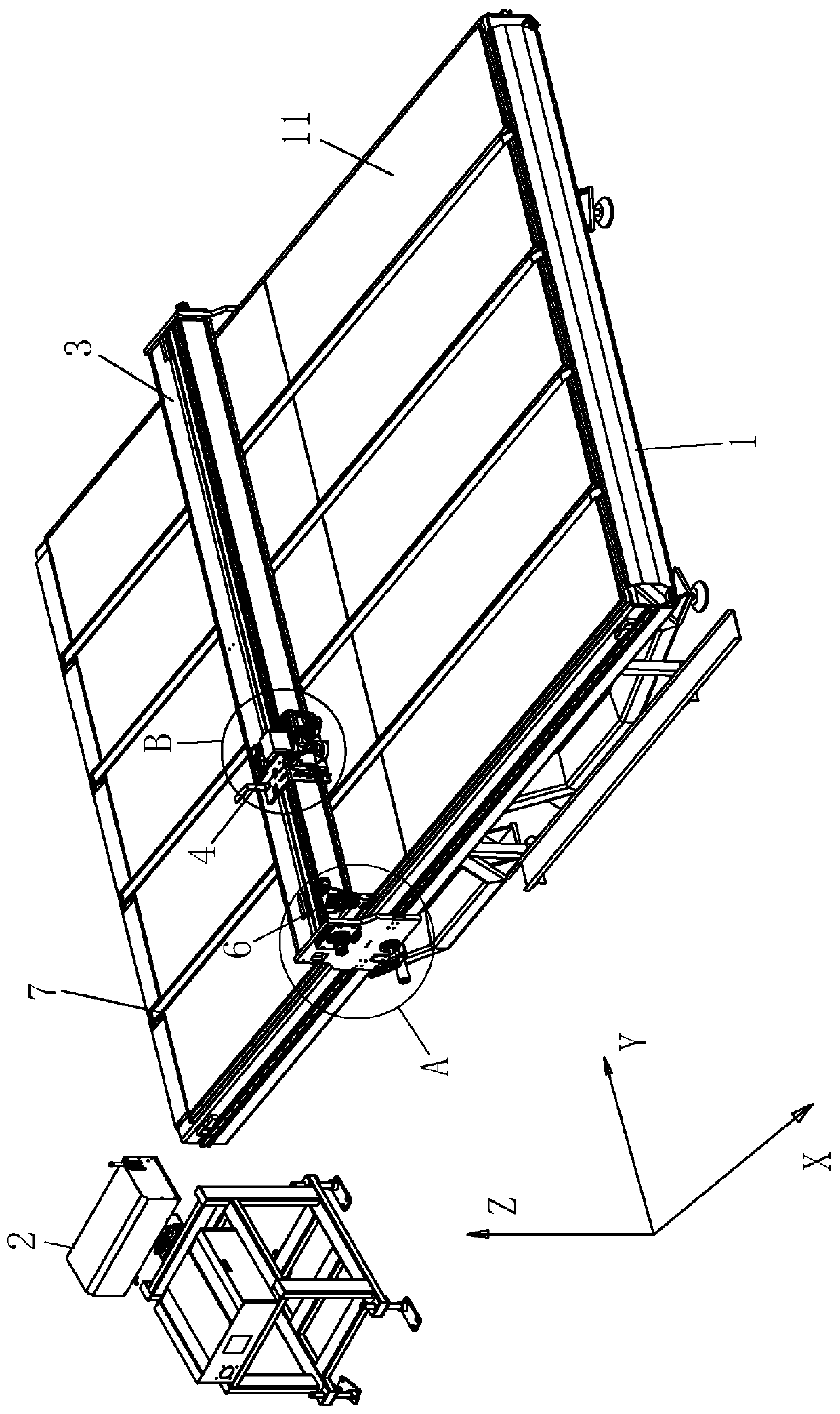
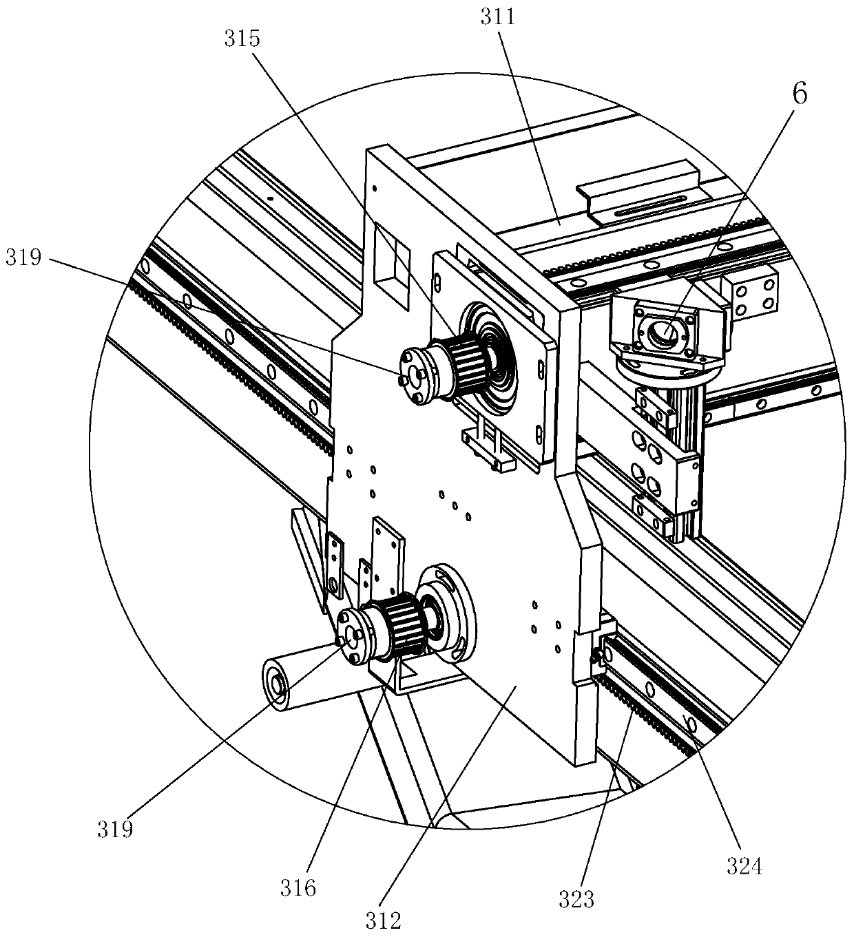
[0077] This embodiment discloses a fully automatic glass laser melting marking equipment, including a frame 1, a laser generator device 2, an X-axis moving beam assembly 3, a Y-axis moving mechanism 4, a vibrating mirror 422, a field mirror 521, an optical fiber Edge-finding probe 525, optical path setting mechanism 6, glass lifting and conveying mechanism 7 and central controller. The spatial Cartesian coordinate system where the device is located refers to figure 1 The coordinate system shown in .

[0078] In this embodiment, the frame 1 is equipped with a glass carrier platform 11 for carrying the glass to be processed; the laser generator device 2 is arr...


PUM


Abstract

The invention relates to full-automatic glass laser melting marking equipment and a working method thereof. The full-automatic glass laser melting marking equipment is characterized in that a glass bearing platform is mounted on a rack, a laser generator device is arranged beside the rack for generating a laser beam, an X-axis moving beam assembly is located above the glass bearing platform and can move in the X-axis direction, a Y-axis moving mechanism is mounted on the X-axis moving beam assembly, an optical path setting mechanism is mounted at one end of the X-axis moving beam assembly andis used for receiving the laser beam generated by the laser generator device and sequentially refracting the laser beam onto a galvanometer and a field lens, an optical fiber edge finding probe, the galvanometer and the field lens are all mounted on the Y-axis moving mechanism, and the field lens can do lifting motion in the Z-axis direction. The marking equipment is perfect in system, simple andreasonable in structure, and capable of performing machining of identifications such as surface bar codes and two-dimensional codes on glass of different specifications, so that the unique identity which cannot be washed and eliminated is endowed to a glass product, and the traceability of machining the product in the subsequent working process of a production line connected with the marking equipment is greatly improved.

Description

technical field [0001] The invention relates to the field of glass processing equipment, in particular to a fully automatic glass laser melting marking equipment and a working method thereof. Background technique [0002] In the glass production process, from the large-size flat original glass to the final finished glass, there are many processes such as cutting, edge grinding, punching, cleaning, tempering, etc. At the same time, in order to improve the cutting rate of the glass, the same raw Glass products of different types, different customers and different batches of orders, and different sizes are placed on the same original glass sheet and cut together for production, which brings problems to the subsequent process. How to confirm the glass order, size specification, Processing requirements, information such as the processing of broken pieces after processing, etc., are issues faced by all glass processing factories. For example, after damaged pieces are patched, ther...

Claims


Application Information

Patent Timeline
IPC IPC(8): B23K26/362B23K26/08B23K26/03B23K26/70
CPCB23K26/032B23K26/0876B23K26/362B23K26/702B23K2103/54
Inventor 魏云峰邱高忠吴春福
Owner 浙江愚工智能设备有限公司
Learn More