Flue gas cyclone distributor for rotary spray desulfurization

A technology of rotary spray and distributor, which is applied in the direction of gas treatment, separation method, and separation of dispersed particles, etc. It can solve the problems of poor mixing intensity of flue gas and desulfurizer slurry, unsatisfactory mixing effect of gas, solid, and liquid, and drying and reaction effects To achieve the effect of enhancing uniformity and stability, improving distribution effect, and simple structure

Pending Publication Date: 2020-02-28
ANHUI XINCHUANG ENERGY SAVING & ENVIRONMENTAL PROTECTION SCI & TECH
View PDF0 Cites 0 Cited by
  • Summary
  • Abstract
  • Description
  • Claims
  • Application Information

AI Technical Summary

Problems solved by technology

[0007] The purpose of the present invention is to solve the unreasonable distribution of flue gas in the flue gas swirl distributor. The flue gas rotates and moves upward after passing through the swirl distributor. Poor, poor drying and reaction effects, resulting in adverse effects; if the inclination angle of the swirl plate is changed to increase the swirl intensity, the vertical velocity component will be reduced and the radial velocity component will be increased, which will also cause gas, solid and liquid mixing effects It is not ideal; at the same time, the poor distribution effect also causes uneven distribution of flue gas, which leads to the problem of low desulfurization efficiency, and a flue gas swirl distributor for rotary spray desulfurization is proposed

Method used


Image

  • Flue gas cyclone distributor for rotary spray desulfurization
  • Flue gas cyclone distributor for rotary spray desulfurization
  • Flue gas cyclone distributor for rotary spray desulfurization

Examples


Embodiment Construction

[0027] The technical solutions of the present invention will be clearly and completely described below in conjunction with the embodiments. Apparently, the described embodiments are only some of the embodiments of the present invention, not all of them. Based on the embodiments of the present invention, all other embodiments obtained by persons of ordinary skill in the art without creative efforts fall within the protection scope of the present invention.

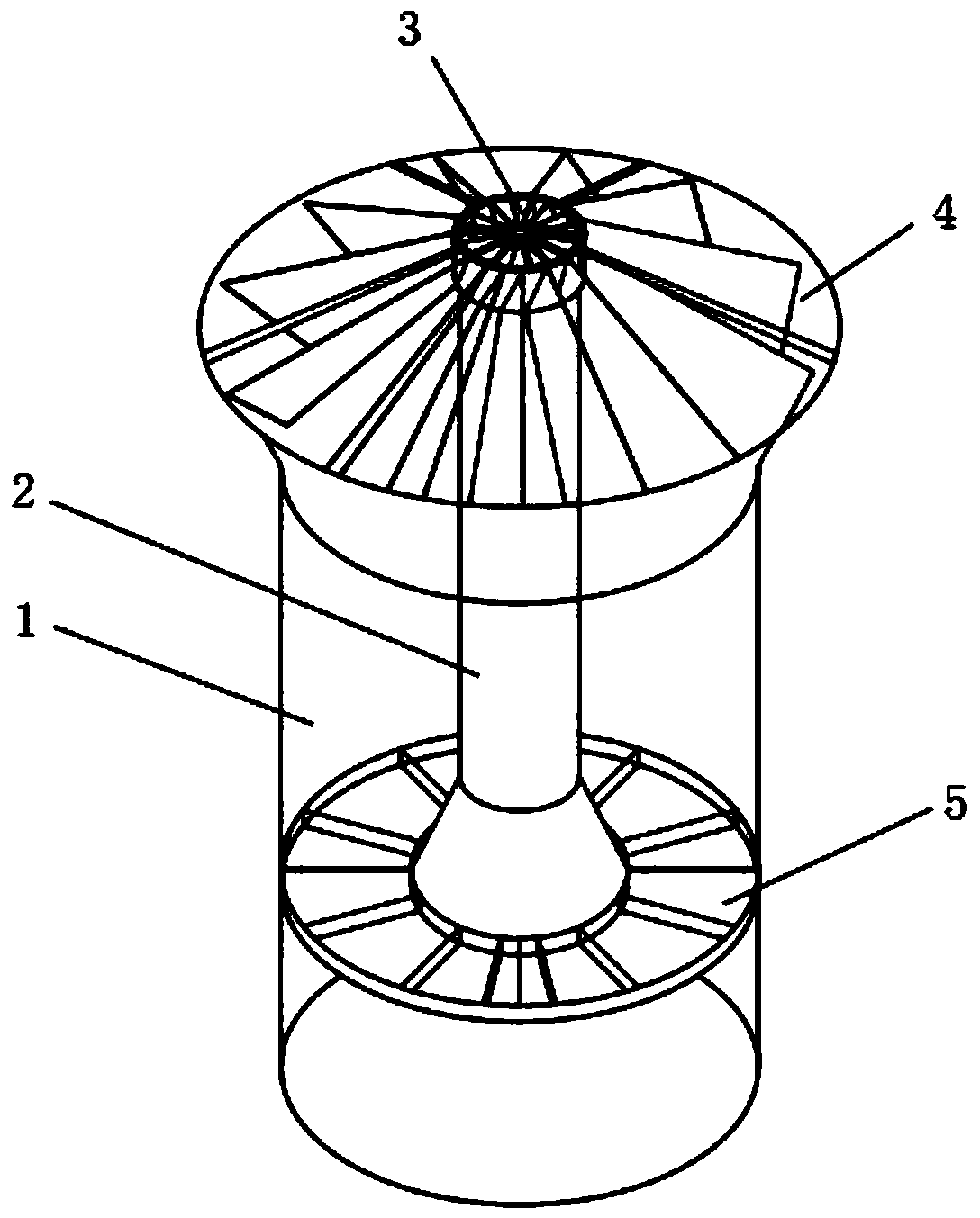
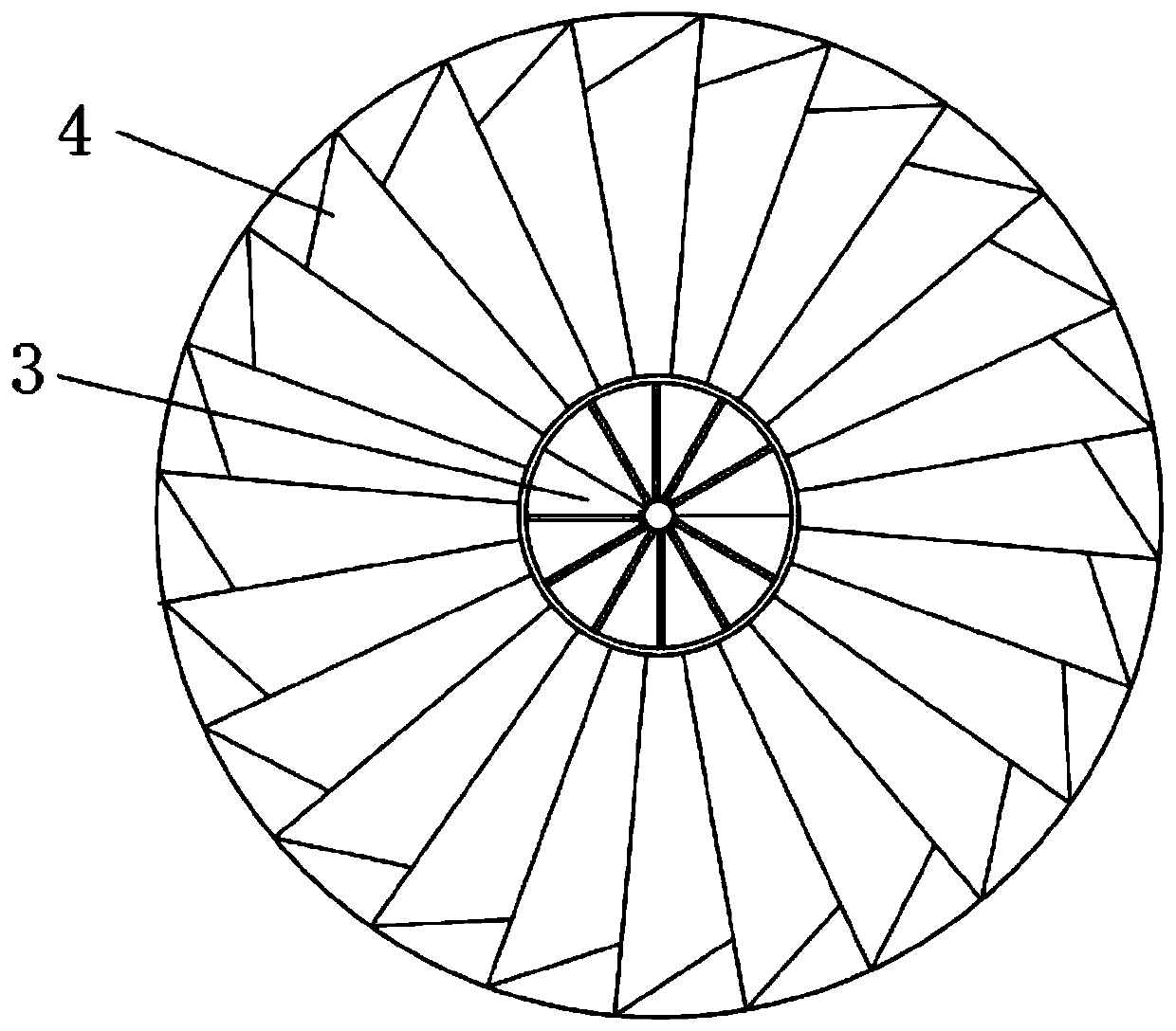
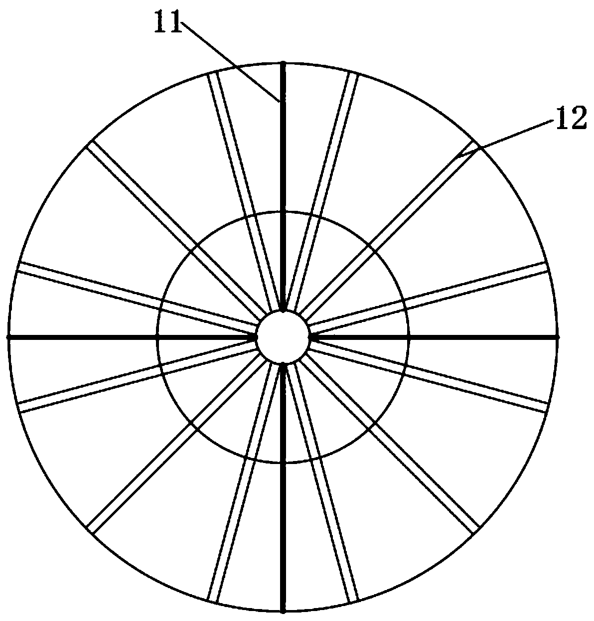
[0028] see Figure 1-3 As shown, a flue gas swirl distributor for rotary spray desulfurization includes an inner flue 2 and an outer flue 1, the inner flue 2 is provided with a cross-shaped bracket 11, and the inner flue 2 passes through the bracket 11 is connected and fixed with the outer flue 1, and a circular flow equalizer 5 is provided at the inlet cross section of the inner flue 2, and several external swirls are arranged on an equal arc between the outlet of the inner flue 2 and the outlet of the outer flue 1. The f...


PUM


Abstract

The invention discloses a flue gas cyclone distributor for rotary spray desulfurization. The flue gas cyclone distributor comprises an inner flue and an outer flue, a support with a cross structure isarranged in the inner flue, the inner flue is fixedly connected to the outer flue through the support, a circular flow equalizer is arranged on the section of an inlet of the inner flue, and a plurality of outer rotational flow pieces are arranged between an outlet of the inner flue and an outlet of the outer flue at equal radian. The beneficial effects of the invention are that: a single flue atthe bottom of a rotary spray desulfurization tower is divided into an inner flue and an outer flue which are combined, rotational flow pieces are mounted at outlets of the inner flue and the outer flue, inclination angles of the outer rotational flow pieces are larger than those of the inner rotational flow pieces, so that flue gas is divided into an upward gas flow with a large velocity component in the vertical direction and a diffusion gas flow with large rotational strength towards the periphery, the convection intensity of flue gas around an atomizing wheel is increased, and the rotational flow intensity of the flue gas in the tower is increased, so that the mixing intensity of the flue gas and a desulfurizing agent is improved, and the desulfurizing efficiency is improved.

Description

technical field [0001] The invention relates to a flue gas swirl distributor, in particular to a flue gas swirl distributor for rotary spray desulfurization, and belongs to the technical field of flue gas swirl distributors. Background technique [0002] SO2 gas is one of the main air pollutants and is the main cause of acid rain. With the rapid development of my country's industrialization, the problem of air pollution caused by SO2 is becoming more and more serious. Facing the severe pollution situation, the Ministry of Ecology and Environment issued the " Opinions on Promoting the Implementation of Ultra-Low Emissions in the Iron and Steel Industry” proposes that by the end of 2025, more than 80% of the national iron and steel enterprises will strive to complete ultra-low emission transformation, and the SO2 concentration limit will be 35mg / Nm3. [0003] The rotary spray desulfurization process is a relatively mature semi-dry desulfurization process, which is widely used b...

Claims


Application Information

Patent Timeline
Patent Type & Authority Applications(China)
IPC IPC(8): B01D53/80B01D53/50
CPCB01D53/50B01D53/80B01D2258/0283
Inventor 胡笳夏勇军吴海彤程灿李丰
Owner ANHUI XINCHUANG ENERGY SAVING & ENVIRONMENTAL PROTECTION SCI & TECH
Why Eureka
Try Eureka