Electric motor with commutator, and manufacturing method of armature and starter motor for engine

a technology of electric motors and commutators, which is applied in the direction of engine starters, machines/engines, power operated starters, etc., can solve the problems of increasing production costs, increasing manufacturing steps, and increasing the axial length of armatures, so as to improve the rotation strength, increase the number of manufacturing steps, and increase the production cost

Inactive Publication Date: 2005-08-04
HITACHI CAR ENG CO LTD +1
View PDF3 Cites 3 Cited by
  • Summary
  • Abstract
  • Description
  • Claims
  • Application Information

AI Technical Summary

Benefits of technology

[0013] As this invention requires no additional member for a lock mechanism and does not increase the number of manufacturing steps pertaining to the lock mechanism, this invention can improve the rotating strength at the connecting part between the armature coil and the commutator and the reliability without increase the production cost.

Problems solved by technology

Further, this method requires many manufacturing steps and a greater axial length of the armature because the leading part of the armature coil axially protrudes from the connecting part.
As for the connecting method of Patent Document 2 which provides a coil retaining member between the armature core and the commutator, this method requires more components to assure the rotating strength of the connecting part of the armature coil and increases the production cost.

Method used


Image

  • Electric motor with commutator, and manufacturing method of armature and starter motor for engine
  • Electric motor with commutator, and manufacturing method of armature and starter motor for engine
  • Electric motor with commutator, and manufacturing method of armature and starter motor for engine

Examples


embodiment 1

[0040] A First Embodiment of this Invention will be Explained Below with Reference to FIG. 1 to FIG. 5

[0041]FIG. 4 shows the whole configuration of a starter 100. The starter 100 receives DC power from a battery (not shown in the drawing) on a vehicle, generates a rotational driving force to start an internal combustion engine (not shown in the drawing) of the vehicle, and transmits the rotational driving force to a ring gear 150 of the engine. The starter 100 of this embodiment is a starter equipped with a reduction gear mechanism and mainly consists of four functional blocks: driving force generating block, driving force transmitting block, driving block, and reduction gear block.

[0042] The driving force generating block generates a rotational driving force to start the engine. The block consists of a DC motor 110. The driving force transmitting block transmits a rotational driving force from the DC motor 110 to the ring gear 150 of the engine and consists of a clutch mechanism 1...

embodiment 2

[0090] A second embodiment of this invention will be explained below with reference to FIG. 6 and FIG. 7.

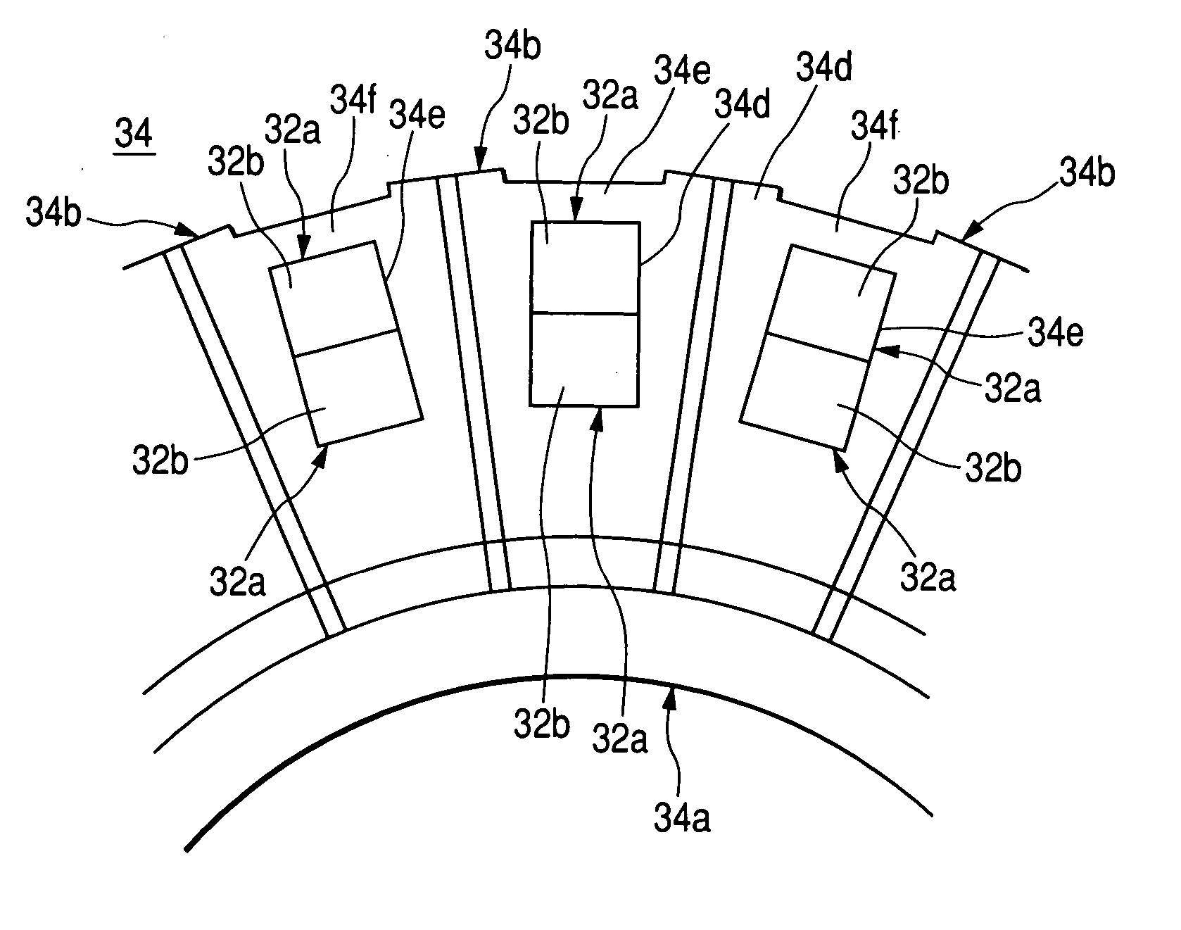
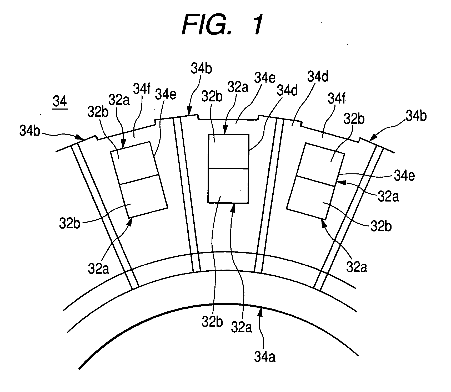
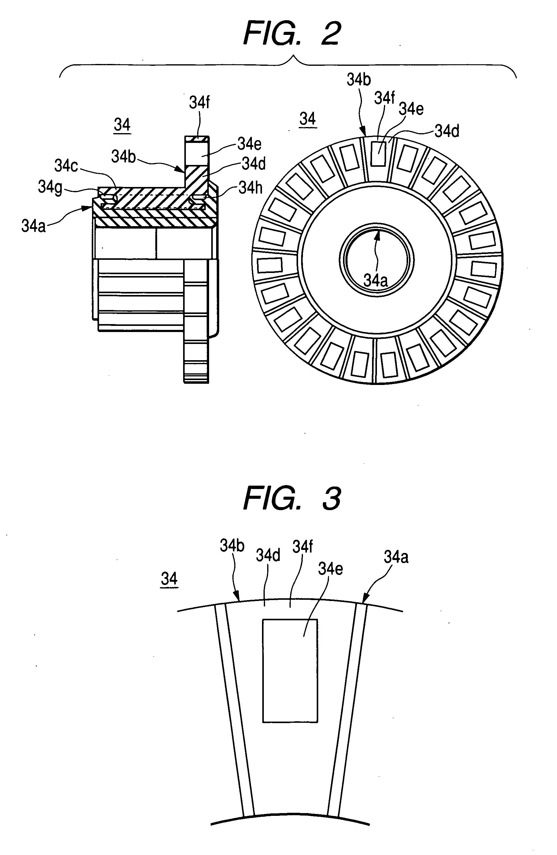
[0091] This embodiment is a variation of Embodiment 1 in which the configurations of the lock member 34f and the coil connecting parts 34e on the vertical section 34d of the commutator segments 34b of the commutator 34 are different from those of Embodiment 1. The other configurations and the armature manufacturing method are the same as those of Embodiment 1. Repetition of the description on the same or similar components will be omitted. Only differences from Embodiment 1 will be explained below.

[0092] This embodiment forms grooves for coil connecting parts 34e. Each groove runs through axially and its end is open on the outer circumference. The circumferential width of the opening is smaller than that of the groove and that of the coil conductor 32a set in the coil connecting part 34e. The opening is located in the circumferential center of the outer side of the groove. Ther...


PUM


Abstract

To accomplish the above object, this embodiment forms the coil connecting parts 34e on the vertical sections 34d of the commutator segments 34b so that the coil conductors 32a may be assembled axially. On the outer circumference of the coil connecting part 34e, this can form the commutator segments 34b in a body with the lock members 34f that prevent the coil conductor 32a from going out in the centrifugal direction from the coil connecting part 34e. Therefore, the rotating strength (the centrifugal strength) of coil conductors 32a can be improved in the coil connecting part 34e without any additional member for the lock member 34f and without increasing the number of manufacturing steps pertaining to the lock member 34f.

Description

CLAIM OF PRIORITY [0001] The present application claims priority from Japanese application serial no. 2004-024961, filed on Feb. 2, 2004, the content of which is hereby incorporated by reference into this application. BACKGROUND OF THE INVENTION [0002] This invention relates to an electric motor with a commutator, a method of manufacturing its armatures, and a starter. [0003] There have been various methods to connect a commutator of an electric motor to an armature coil of the motor. For example, Japanese laid-open Patent Publication No. Hei 08-275464 and Japanese Laid-open Patent Publication No. Hei 07-67305 disclose such methods. [0004] Japanese laid-open Patent Publication No. Hei 08-275464 discloses a method of connecting a commutator to an armature coil by fitting the leading part of the armature coil to an open groove on a commutator segment and electrically crimping the open groove. Further, Patent Document 1 improves the rotating strength of the connecting part of the armat...

Claims


Application Information

Patent Timeline
Patent Type & Authority Applications(United States)
IPC IPC(8): F02N15/02F02N11/00F02N15/06H01R39/32H01R43/06H02K13/04H02K15/04H02K23/26
CPCF02N11/00H02K13/04H01R43/06H01R39/32
Inventor ABE, MITSUTOSHIYANAGAWA, NORIOKARINO, KIMIJI
Owner HITACHI CAR ENG CO LTD
Why Eureka
Try Eureka