Motor dynamic braking circuit and motor dynamic braking method

A brake circuit, dynamic technology, applied in circuit devices, emergency protection circuit devices for limiting overcurrent/overvoltage, emergency protection circuit devices, etc., can solve the problem of increasing resistance burden, slow motor stop, dynamic braking effect impact and other issues, to achieve the effect of simplifying system wiring, reducing cost and volume, and reducing PCB layout area

Active Publication Date: 2020-02-25
NANJING ESTUN AUTOMATION CO LTD
View PDF8 Cites 4 Cited by
  • Summary
  • Abstract
  • Description
  • Claims
  • Application Information

AI Technical Summary

Problems solved by technology

In the traditional system, the dynamic braking module can only be placed on the AC side. If it is placed on the DC side, the terminal voltage of the dynamic braking module will be clamped by the bus capacitor voltage, and the dynamic braking effect will be greatly affected. The dynamic resistor also bears the additional discharge of the bus capacitance energy, which increases the resistance burden

Method used


Image

  • Motor dynamic braking circuit and motor dynamic braking method
  • Motor dynamic braking circuit and motor dynamic braking method
  • Motor dynamic braking circuit and motor dynamic braking method

Examples


Embodiment

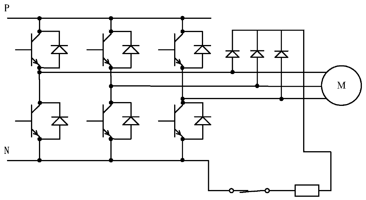
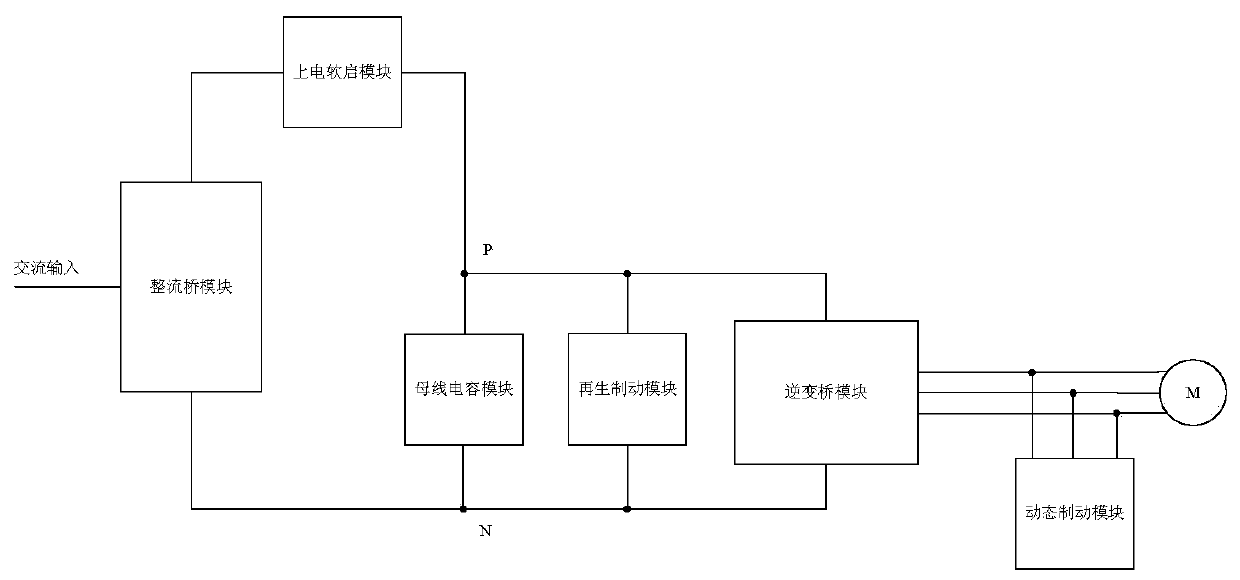
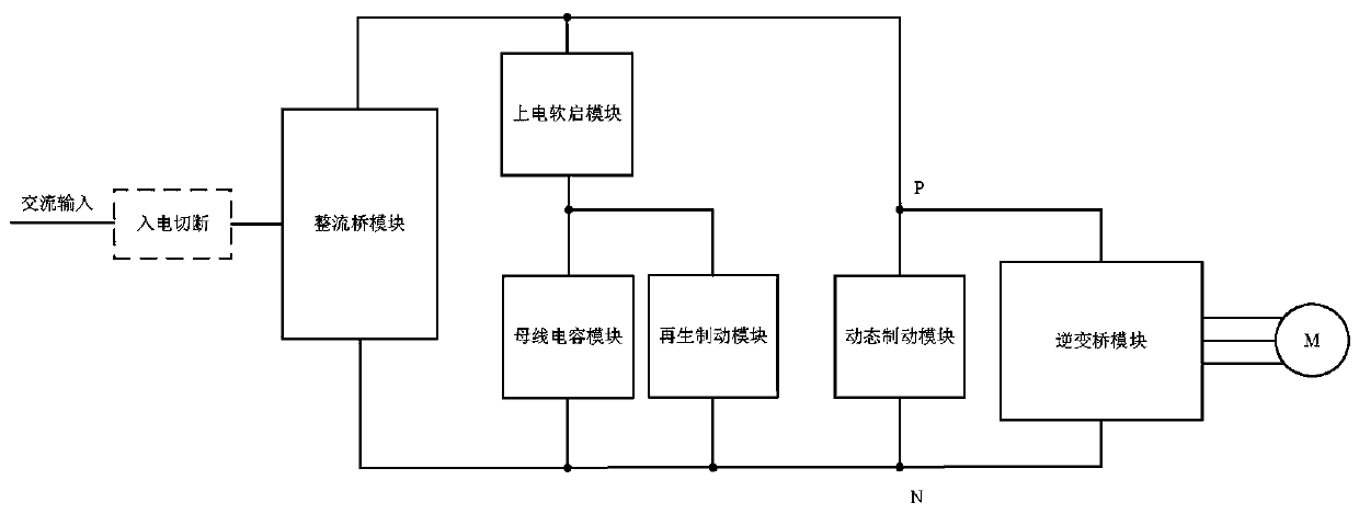
[0032] image 3 Shown is the motor dynamic brake circuit proposed by the present invention. The power frame is composed of a rectifier bridge module, a power-on soft start module, a bus capacitor module, a regenerative brake module, an inverter bridge module and a dynamic brake module. The connection topology is different from traditional solutions. After the AC power is rectified by the rectifier bridge module, it is filtered by the bus capacitor and transformed into a DC bus P / N with stable voltage, and then the DC power is converted into AC power by the inverter bridge module to drive the motor. One end of the power-on soft start module is connected to the positive P of the bus bar, the other end is connected to one end of the bus capacitor module and the regenerative braking module, the other end of the bus capacitor module and the regenerative braking module is connected to the negative N of the bus bar, and the dynamic braking module is directly connected to On the DC b...


PUM


Abstract

The invention discloses a motor dynamic braking circuit and a motor dynamic braking method. After being rectified by a rectifier bridge module, alternating current is converted into direct current busP / N with stable voltage through bus capacitor filtering, and then the direct current is converted into the alternating current through an inverter bridge module to drive the motor; one end of a power-on soft start module is connected to the bus positive P, the other end is connected with one ends of a bus capacitor module and a regenerative braking module, the other ends of the bus capacitor module and the regenerative braking module are connected to the bus negative N, and a dynamic braking module is directly connected to the direct current bus P / N. The dynamic braking circuit completely multiplexes the body diodes of the inverter bridge module to achieve rectification, three additional diodes do not need to be additionally arranged on each axis, the system cost is reduced, and the PCB area is reduced; the dynamic braking module shared by the multi-axis common bus system can be supported without adding any additional wiring, so that the system wiring is simplified, and the cost of wiring terminals and cables is reduced.

Description

technical field [0001] The invention relates to a motor dynamic braking circuit and a motor dynamic braking method. Background technique [0002] Dynamic braking is widely used in motor-driven power electronic conversion equipment. When an emergency alarm occurs in the system, or the system is powered off, or the system needs to be stopped in an emergency, the dynamic braking will work, and the motor will be stopped quickly and safely to avoid causing damage. Equipment damage, personal injury, etc. Several common topologies for dynamic braking are as follows: [0003] Japanese patent document JP3863529B2 discloses a dynamic braking topology diagram, which is also the most simple and common dynamic braking topology. When receiving a dynamic braking demand, the system stops PWM transmission, then starts the dynamic braking circuit, pulls in the relay, and The energy in the motor windings is dissipated in the resistive loop, stopping the motor quickly. In the case of low-pow...

Claims


Application Information

Patent Timeline
IPC IPC(8): H02P3/22H02H9/04
CPCH02H9/04H02P3/22
Inventor 姚瑱杜鑫钱巍
Owner NANJING ESTUN AUTOMATION CO LTD
Why Eureka
Try Eureka