
Paper feeding device and image forming apparatus

a feeding device and paper feeding technology, applied in the direction of thin material processing, instruments, article separation, etc., can solve the problems of poor operability, violent jumping of paper feeding cassettes, paper feeding cassettes, etc., and achieve the effect of enhancing the operability of drawing out or inserting paper feeding cassettes

Inactive Publication Date: 2011-01-04
FUJIFILM BUSINESS INNOVATION CORP
View PDF21 Cites 14 Cited by
  • Summary
  • Abstract
  • Description
  • Claims
  • Application Information

AI Technical Summary

Benefits of technology

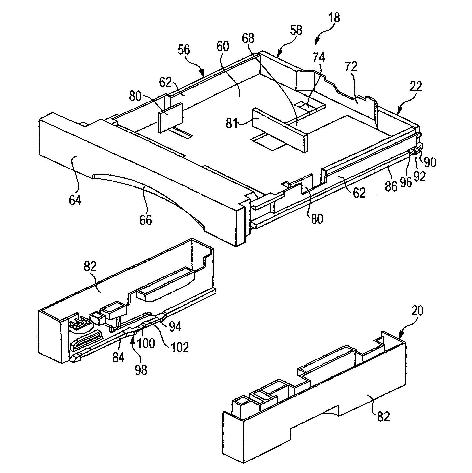
The invention provides a paper feeding device with improved operability for drawing out or inserting a paper feeding cassette. The device includes a guide part that allows for smooth operation of the cassette along a rectilinear line. A stopper is provided to lock the cassette in place when drawn out, and a stopper releasing part is integrally formed with the guide part. The device also includes a first member and a second member that are slidably connected, and the stopper is provided on the second member. The second member is contained inside the paper feeding device body, and the device further includes a backward area beyond the insertion inlet of the cassette, which restrains movement of the cassette in a direction perpendicular to the inserting direction. These features enhance the usability of the device without adding components or increasing the number of components.

Problems solved by technology

In case where the paper feeding cassette is drawn out with no resistance, it is concerned that the paper feeding cassette may jump out violently, and a backward end of the paper feeding cassette may fall on a foot of a user.
For example, the paper feeding cassette must be inclined without straightly inserting, and operability has been poor.
Therefore, there has been a problem that the number of components has increased.

Method used


Image

  • Paper feeding device and image forming apparatus
  • Paper feeding device and image forming apparatus
  • Paper feeding device and image forming apparatus

Examples


Embodiment Construction

[0026]Now, an embodiment of the invention will be described referring to the drawings.

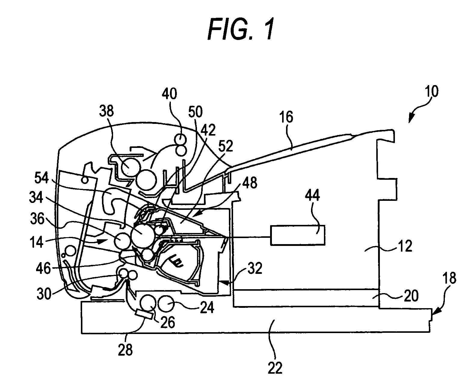
[0027]FIG. 1 schematically shows an image forming apparatus 10 according to the embodiment of the invention. The image forming apparatus 10 includes an image forming apparatus body 12. Image forming means 14 is mounted inside the image forming apparatus body 12, and a discharge part 16 is provided in an upper part of the image forming apparatus body 12. At the same time, a paper feeding device 18 of one step, for example, is provided in a lower part of this image forming apparatus body 12.

[0028]The paper feeding device 18 includes a paper feeding device body 20, and a paper feeding cassette 22 in which sheets of paper are contained. The paper feeding cassette 22 is provided in the paper feeding device body 20 so as to be freely drawn out. Paper feeding rolls 24, 26 are arranged on the paper feeding device body 20, and the sheets of paper stacked on the paper feeding cassette 22 will be transferred ...


PUM


Abstract

A paper feeding device including: a paper feeding device body; a paper feeding cassette which is contained in the paper feeding device body so as to be freely drawn out; a guide part for guiding the paper feeding cassette with respect to the paper feeding device body along a substantially rectilinear line; a stopper for locking the paper feeding cassette on the way of drawing out the paper feeding cassette from the paper feeding device body; and a stopper releasing part which is integrally formed with the guide part and adapted to be flexed according to operation of drawing out the paper feeding cassette, thereby to release the lock of the stopper.

Description

BACKGROUND OF THE INVENTION[0001]1. Field of the Invention[0002]The present invention relates to a paper feeding device and an image forming apparatus provided with the same.[0003]2. Background Art[0004]In an image forming apparatus, there is employed a paper feeding device for feeding paper on which an image is to be formed. The paper feeding device of this type has a paper feeding cassette which is contained in a paper feeding device body so as to be freely drawn out, and the paper can be replenished, by drawing out the paper feeding cassette from the paper feeding device body.[0005]In case where the paper feeding cassette is drawn out with no resistance, it is concerned that the paper feeding cassette may jump out violently, and a backward end of the paper feeding cassette may fall on a foot of a user. For preventing such phenomenon, there has been known a paper feeding device in which the paper feeding cassette is once locked, as a safety net on occasion of drawing out the paper...

Claims


Application Information

Patent Timeline
Patent Type & Authority Patents(United States)
IPC IPC(8): B65H1/00
CPCB65H1/26G03G15/6502B65H2405/11164
Inventor KOBAYASHI, YUSUKE
Owner FUJIFILM BUSINESS INNOVATION CORP
Learn More