Coke conveying chute

A technology for conveying chute and coke, applied in conveyors, transportation and packaging, chute and other directions, can solve the problems of heavy maintenance stress, large material consumption, environmental pollution, etc., to reduce maintenance costs, improve conveying efficiency, and easy to operate methods. Effect

Inactive Publication Date: 2020-02-25
徐州东兴能源有限公司
View PDF0 Cites 0 Cited by
  • Summary
  • Abstract
  • Description
  • Claims
  • Application Information

AI Technical Summary

Problems solved by technology

The recovered and purified coke oven gas produced in the coking process is not only a fuel with high calorific value, but also an important industrial raw material for organic synthesis; the most commonly used in the coke workshop is the coke guide steel pipe for conveying coke, because the coke line When conveying coke, a large amount of corrosive mist is produced, and the coke guide steel pipe is severely corroded; the existing coke guide steel pipe wears quickly, and due to the large impact force and no corresponding buffer device, coke and coke are often scattered outward. Particles and coke powder will pollute the environment, which is not conducive to clean production, and increase the burden of cleaning and sanitation for employees; frequent replacement of steel pipes, high material consumption, increased maintenance costs, and heavy maintenance, which is not conducive to daily maintenance; therefore, in order to be able to solve the above Problem Designing a coke conveying chute

Method used


Image

  • Coke conveying chute
  • Coke conveying chute
  • Coke conveying chute

Examples


Embodiment Construction

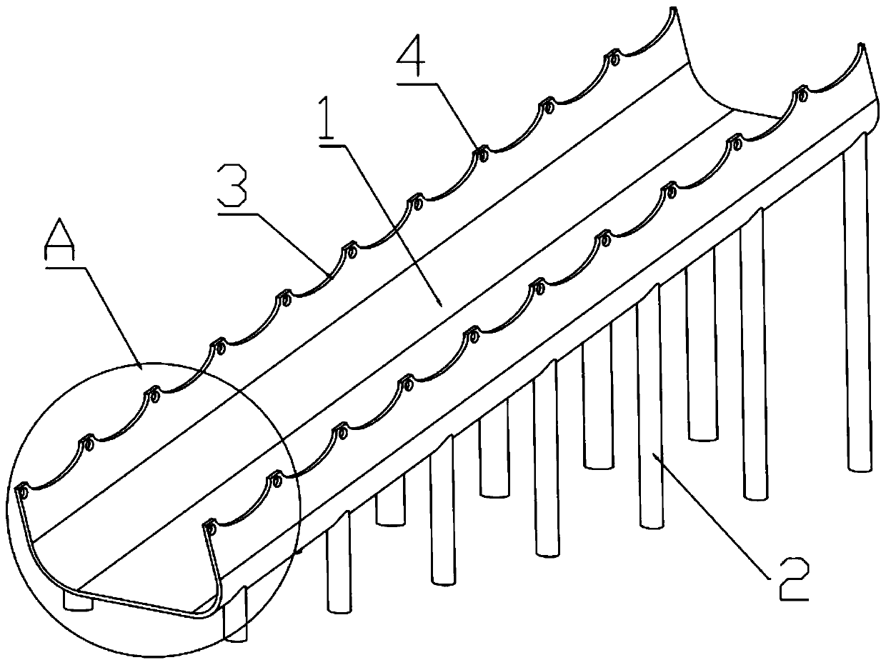
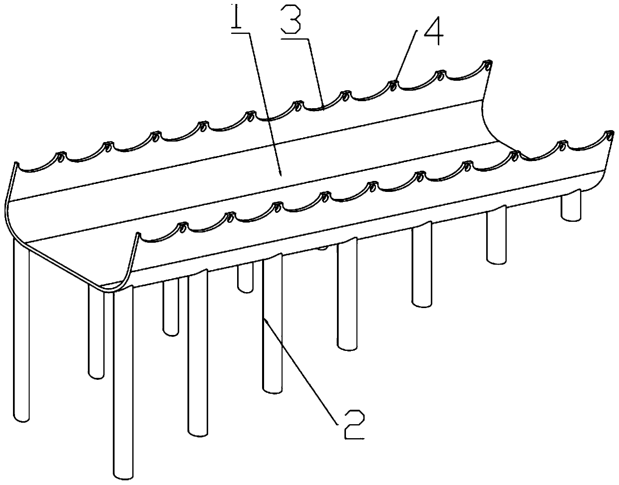
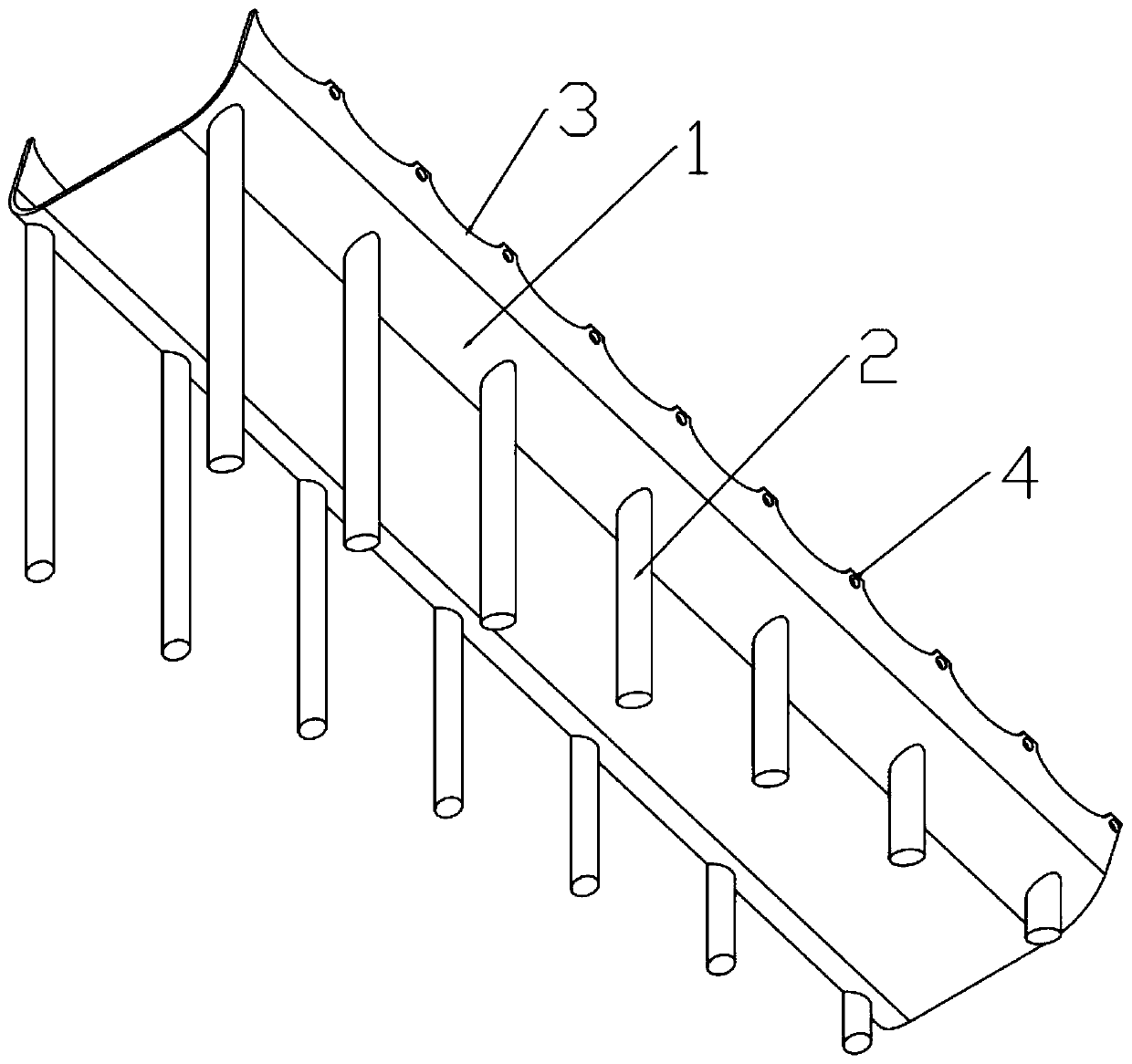
[0018] A coke conveying chute of the present invention will be further described in detail below in conjunction with the accompanying drawings.

[0019] combined with Figure 1-4 , a coke conveying chute, comprising a U-shaped chute body 1, the U-shaped chute body 1 is placed obliquely, the lower end of the U-shaped chute body 1 is provided with a support rod 2, and the support rods 2 are symmetrically distributed on On both sides of the U-shaped chute body 1, the support rods 2 are evenly distributed in the extending direction of the U-shaped chute body 1, and the number of the support rods 2 is not less than four;

[0020] The edges of both sides of the U-shaped chute body 1 are provided with notches 3, and the notches 3 are evenly distributed in the extending direction of the U-shaped chute body 1, and the edges of both sides of the U-shaped chute body 1 Through-holes 4 are provided between adjacent notches 3 , and the through-holes 4 are evenly distributed along the exten...


PUM


Abstract

The invention discloses a coke conveying chute which comprises a U-shaped sliding groove body. The U-shaped sliding groove body is obliquely arranged. Supporting rods are arranged at the lower end ofthe U-shaped sliding groove body. The supporting rods are symmetrically distributed on the two sides of the U-shaped sliding groove body. The supporting rods are evenly distributed in the extending direction of the U-shaped sliding groove body. At least four supporting rods are arranged. Notches are formed in the edge positions of the two sides of each U-shaped sliding groove body. The notches areevenly distributed in the extending direction of the U-shaped sliding groove body. A through hole is formed between every two adjacent notches at the edge positions of the two sides of the U-shaped sliding groove body, and the through holes are evenly distributed in the extending direction of the U-shaped sliding groove body. Daily maintenance is convenient, replacement is simple, operation is easy, the overhaul period is greatly prolonged, the overhaul cost is reduced, and the labor cost is reduced. The cost is saved, the workload of staff is reduced, the structure is simple, an operation method is easy to master, continuous use can be achieved after one-time installation, and the coke conveying efficiency is improved.

Description

technical field [0001] The invention relates to the technical field of coke conveying devices, in particular to a coke conveying chute. Background technique [0002] Coking generally refers to the process of carbonization and zooming of organic substances. In the dry distillation of coal, it refers to high temperature dry distillation. In petroleum processing, coking is the abbreviation of residual oil coking, which refers to the deep cracking and condensation of heavy oil (such as heavy oil, vacuum residue, cracked residue and even soil asphalt) at a high temperature of about 500 °C Reaction, the process of producing gas, gasoline, diesel oil, wax oil and petroleum coke. Bituminous coal is heated to 950-1050°C in the absence of air, and finally made into coke after drying, pyrolysis, melting, bonding, solidification, shrinkage and other stages. This process is called high-temperature coking. Coke obtained from high temperature coking is used for blast furnace smelting, c...

Claims


Application Information

Patent Timeline
Patent Type & Authority Applications(China)
IPC IPC(8): B65G11/02
CPCB65G11/02B65G2201/04
Inventor 陈金东林晓
Owner 徐州东兴能源有限公司
Why Eureka
Try Eureka