Heat exchanger and refrigeration cycle device
A technology for heat exchangers and refrigerants, applied in heat exchange equipment, refrigerators, refrigeration components, etc., can solve the problems of reduced heat exchanger performance, reduced liquid refrigerant distribution performance, etc., to prevent the reduction of heat exchange performance, The effect of improving heat exchange performance
- Summary
- Abstract
- Description
- Claims
- Application Information
AI Technical Summary
Problems solved by technology
Method used
Image
Examples
Embodiment approach 1
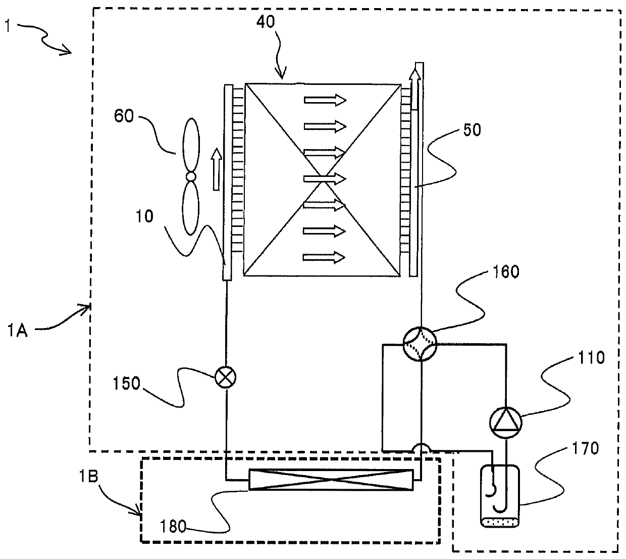
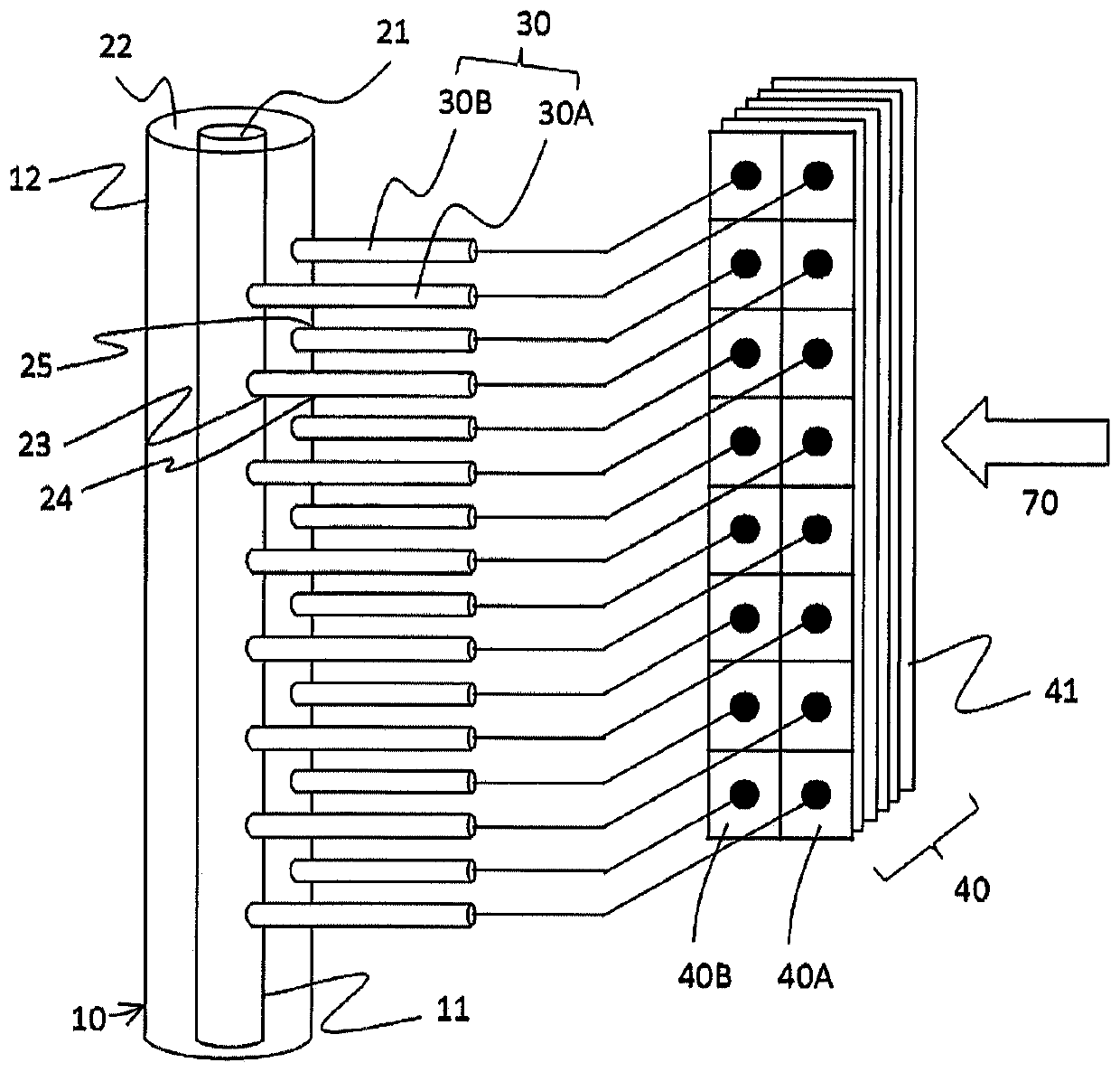
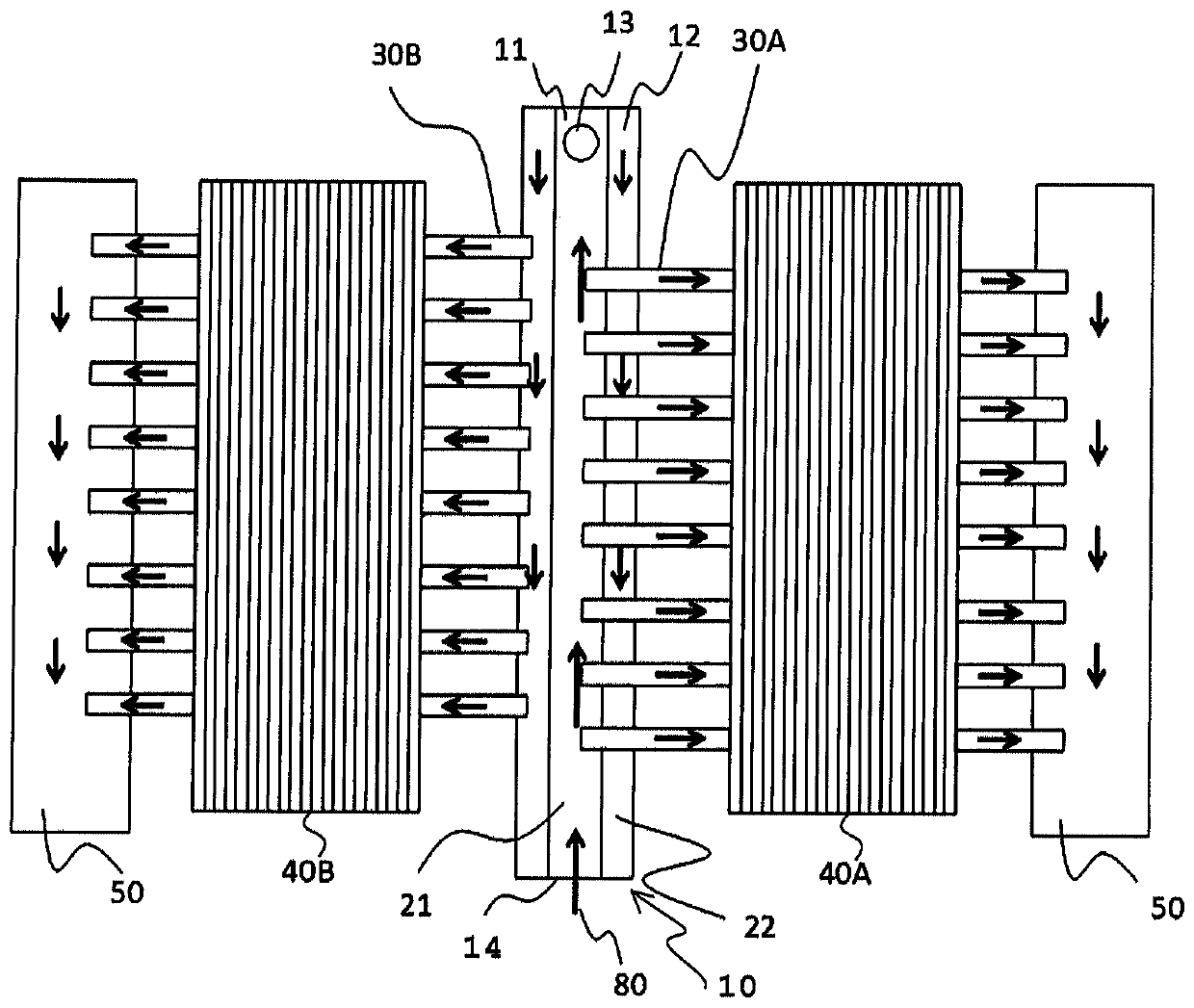
[0059] figure 1 It is a diagram schematically showing the refrigerant circuit configuration of the refrigeration cycle apparatus according to Embodiment 1 of the present invention. figure 2 It is a figure which schematically shows the structure of the header refrigerant distributor of Embodiment 1. The refrigeration cycle apparatus 1 according to Embodiment 1 is an air-conditioning apparatus for air-conditioning a room to be air-conditioned, and is configured to include a heat source-side unit 1A and a use-side unit 1B. The heat source side unit 1A discharges or supplies air-conditioning heat by constituting a refrigeration cycle in which a refrigerant circulates together with the utilization side unit 1B. The heat source side unit 1A is installed outdoors. The heat source side unit 1A has a compressor 110 , a flow path switcher 160 , a heat source side heat exchanger 40 , an expansion device 150 , an accumulator 170 , and a fan 60 . The usage-side unit 1B is installed in ...
Embodiment approach 2
[0077] refer to Figure 10 ~ Figure 13 Embodiment 2 of the present invention will be described. exist Figure 10 ~ Figure 13 In the description, the same reference numerals are assigned to the same or equivalent parts as those in Embodiment 1, and a part of the description of the configuration that overlaps with Embodiment 1 is omitted. Figure 10 It is a figure which schematically shows the structure of the header refrigerant distributor of Embodiment 2 of this invention. The second embodiment differs from the first embodiment in that the heat source side heat exchanger 40 is composed of three rows of heat exchanger cores. In Embodiment 2, the heat source side heat exchanger 40 has a first row of heat exchanger cores 40A, a second row of heat exchanger cores 40B, and a third row of heat exchanger cores 40C from the windward side. A heat transfer tube 30A is connected to the inner tube 11 , and a heat transfer tube 30B is connected to the outer tube 12 . The heat transfer ...
Embodiment approach 3
[0083] refer to Figure 14 ~ Figure 18 Embodiment 3 of the present invention will be described. exist Figure 14 ~ Figure 18 In the first embodiment and the second embodiment, the same parts or corresponding parts are given the same reference numerals, and the description of the configuration overlapping with the first embodiment and the second embodiment is partially omitted. Figure 14 It is a figure conceptually showing the structure of the heat source side heat exchanger concerning Embodiment 3 of this invention. The header refrigerant distributor 10 includes an inner tube 11 and an outer tube 12 and has a double-tube structure. The inner tube flow path 21 is defined by the inner side of the inner tube 11 . The annular flow path 22 is defined by the outer side of the inner tube 11 and the inner side of the outer tube 12, and its cross-sectional shape is annular. Insertion holes 23 into which the heat transfer tubes 30A are inserted are formed in the inner tube 11 , and...
PUM
 Abstract
Description
Claims
Application Information
 - Generate Ideas
- Intellectual Property
- Life Sciences
- Materials
- Tech Scout
- Unparalleled Data Quality
- Higher Quality Content
- 60% Fewer Hallucinations
Browse by: Latest US Patents, China's latest patents, Technical Efficacy Thesaurus, Application Domain, Technology Topic, Popular Technical Reports.
© 2025 PatSnap. All rights reserved.Legal|Privacy policy|Modern Slavery Act Transparency Statement|Sitemap|About US| Contact US: help@patsnap.com


