
Broadband filtering antenna based on grid slotted patches

A filter antenna and patch technology, which is applied in the direction of antenna grounding device, antenna grounding switch structure connection, waveguide device, etc., can solve the problems of antenna gain and waveform influence, non-omnidirectional filtering, limited bandwidth of filter antenna, etc., to achieve The effect of light weight, simple processing, and low processing cost

Pending Publication Date: 2020-02-21
SOUTH CHINA UNIV OF TECH
View PDF0 Cites 6 Cited by
  • Summary
  • Abstract
  • Description
  • Claims
  • Application Information

AI Technical Summary

Problems solved by technology

[0006] In general, in the existing work, there are many studies on the design of broadband antennas and filter antennas, but many designed filter antennas have limited bandwidth or only filter in a certain direction, not all directions.
Some methods form multi-tuning loops by adding gaps and other methods to achieve bandwidth widening and filtering, but the gain and waveform of the antenna will be affected
In order to overcome the problem of narrow bandwidth caused by designing filter antennas using the design method of filter synthesis, the present invention proposes a broadband filter antenna based on grid slotted patch

Method used


Image

  • Broadband filtering antenna based on grid slotted patches
  • Broadband filtering antenna based on grid slotted patches
  • Broadband filtering antenna based on grid slotted patches

Examples


Embodiment Construction

[0024] The present invention will be further described below in conjunction with specific examples.

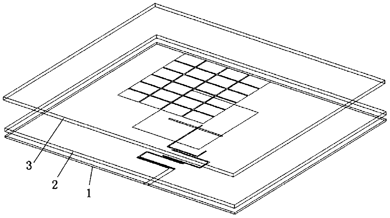
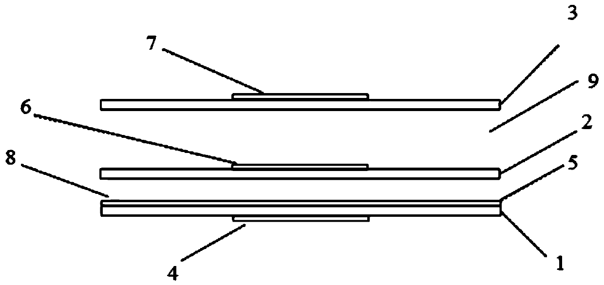
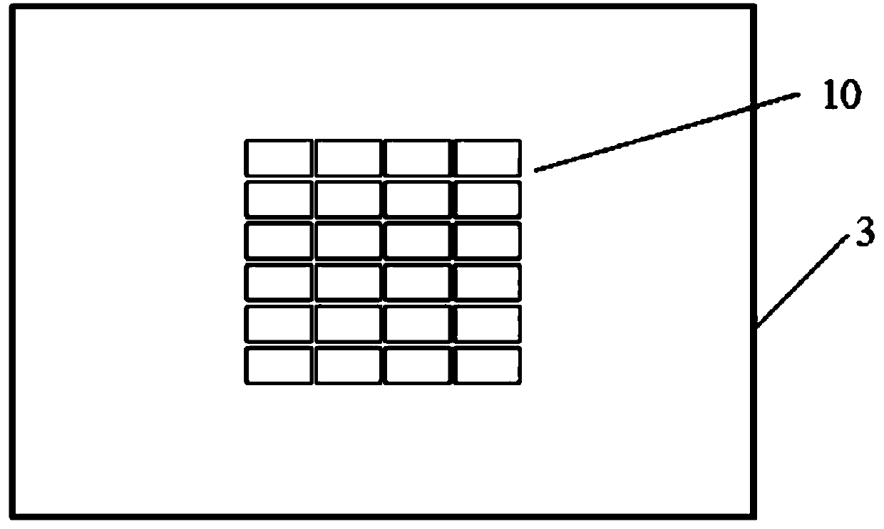
[0025] see Figure 1 to Figure 5 As shown, the broadband filter antenna based on grid slotted patch provided in this embodiment includes a first dielectric plate 1, a second dielectric plate 2 and a third dielectric plate 3; the second dielectric plate 2 is located in the first Above the dielectric board 1, there is a first air layer 8 between them. The main function of the first air layer 8 is to increase the gain of the antenna; the third dielectric board 3 is located above the second dielectric board 2, and there is a second air layer 8 between them Two air layers 9, the second air layer 9 is mainly in order to reduce the reflection coefficient of the antenna in the bandwidth; the upper surface of the third dielectric board 3 is formed with a third copper clad layer 7, and the third copper clad layer 7 is provided with There are grid slotted patch 10, the grid slotted patc...


PUM


Abstract

The invention discloses a broadband filtering antenna based on grid slotted patches. The antenna comprises a first dielectric plate, a second dielectric plate and a third dielectric plate which are sequentially arranged from bottom to top; a first air layer exists between the first dielectric plate and the second dielectric plate; a second air layer exists between the second dielectric plate and the third dielectric plate; a third copper-clad layer is formed on the upper surface of the third dielectric plate, and a grid slotted patch is arranged on the third copper-clad layer; a second copper-clad layer is formed on the upper surface of the second dielectric plate, and a rectangular patch is arranged on the second copper-clad layer; the upper surface of the first dielectric plate is provided with a grounding plate, the lower surface of the first dielectric plate is provided with a first copper-clad layer, the grounding plate is provided with a coupling aperture, the first copper-clad layer is provided with first, second and third half-wavelength U-shaped resonators and a coupling feeder line, and the upper and lower surfaces of the first dielectric plate are provided with input ports. The four-order filtering antenna is comprehensively designed on the basis of a filter and stably works within the range of 2.27 GHz to 2.57 GHz, S11 is smaller than -10 dB, the gain is kept about7.5 dBi, and the whole antenna is simple and compact in structure, convenient to machine and low in cost.

Description

technical field [0001] The invention relates to the technical field of antennas, in particular to a broadband filter antenna based on grid slotted patches. Background technique [0002] With the rapid development of wireless communication and the commercialization of 5G communication systems, there are higher requirements for the communication capacity and transmission rate of wireless communication systems. In addition, 5G communication systems have certain requirements for the filtering characteristics of antennas. Patch antennas are widely used in wireless communication systems due to their light weight, small size, easy conformality, easy processing, and low cost. However, microstrip patch antennas are often limited by their narrow operating bandwidth. For the bandwidth expansion of the patch antenna, many scholars have proposed many broadband filter patch antenna technologies through continuous improvement and research on its characteristics. However, some methods wil...

Claims


Application Information

Patent Timeline
IPC IPC(8): H01Q1/38H01Q1/48H01Q1/50H01P1/203
CPCH01P1/20381H01Q1/38H01Q1/48H01Q1/50
Inventor 陈付昌向凯燃
Owner SOUTH CHINA UNIV OF TECH
Learn More