
Water and oil temperature sensor for automobile and manufacturing method thereof

The technology of an oil temperature sensor and its production method, which is applied in the field of vehicle sensors, can solve the problems of easy breakage of the engine, crushing of the ceramic sensor head, inconsistent thermal expansion and cold contraction, etc., and achieve the effect of saving the production cost of the closure

Inactive Publication Date: 2020-02-21
成都肯保捷芯辰传感器有限公司
View PDF5 Cites 2 Cited by
  • Summary
  • Abstract
  • Description
  • Claims
  • Application Information

AI Technical Summary

Problems solved by technology

The car engine runs fast when it is working, resulting in high-frequency vibration. Since the chip inside the sensor probe of the water and oil temperature sensor is a ceramic sensor head, it is easy to break during the vibration of the engine running. Therefore, it is necessary to ensure the anti-vibration or vibration resistance of the water and oil temperature sensor. Anti-shake performance
The gap between the ceramic sensing head and the casing shell is filled with epoxy resin or other filling glue inside the sensing probe of the existing water and oil temperature sensor, and the epoxy resin has hardness after curing, and there is also the high-frequency vibration of the ceramic sensing head in the engine. In addition, during the temperature rise of the engine, the ratio of thermal expansion and contraction between the epoxy resin layer and the sensor shell is inconsistent, and the ceramic sensor head will also be crushed under stress.

Method used


Image

  • Water and oil temperature sensor for automobile and manufacturing method thereof
  • Water and oil temperature sensor for automobile and manufacturing method thereof

Examples


specific Embodiment

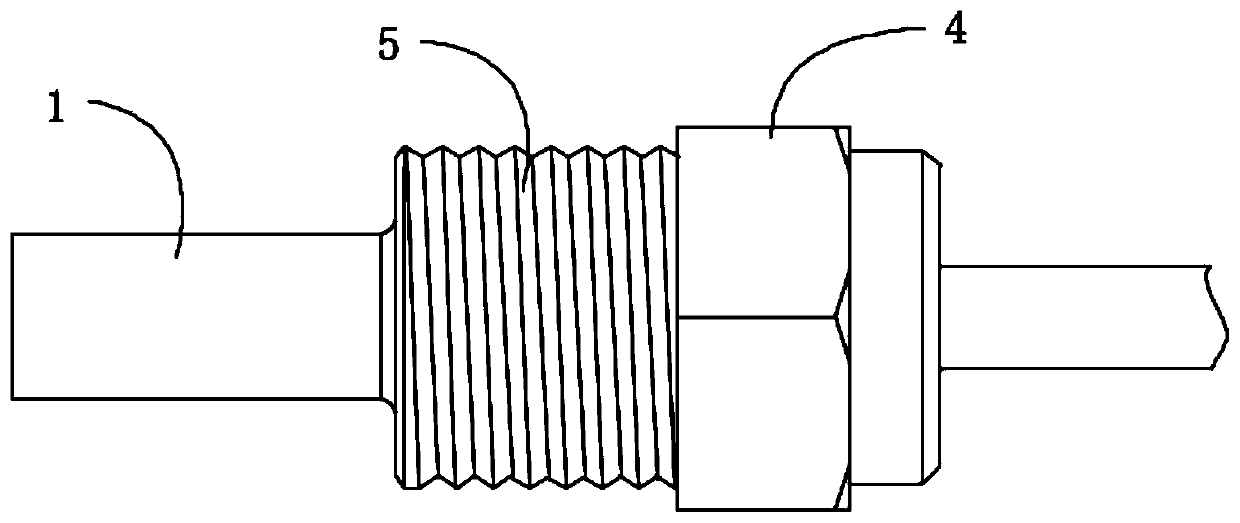
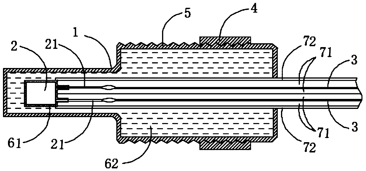
[0023] see Figure 1-2 Shown, the specific embodiment that the present invention provides is as follows:

[0024] A kind of automobile water and oil temperature sensor of the present embodiment, comprises induction head shell 1, ceramic induction head 2, two wires 3, fixing nut 4 and sheath assembly; Two pins of described ceramic induction head 2 terminals 21 and the two wires 3 are welded and fixed respectively, such as connecting the pins and the wires through resistance welding; the ceramic induction head 2 and the two wires 3 are installed in the induction head housing 1 and there is a gap between the induction head housing, so The fixed nut is fastened and installed with the tail of the sensor head housing, and the outer wall of the tail of the sensor head housing 1 is provided with a mounting thread 5, and the sheath assembly is used to isolate the two wires to insulate the two wires.

[0025] In a preferred embodiment, the ceramic induction head and the induction head ...


PUM


Abstract

The invention discloses a water and oil temperature sensor for an automobile and a manufacturing method thereof. The water and oil temperature sensor comprises a sensing head shell, a ceramic sensinghead, two conductive wires, a fixed nut and a sheath assembly. Two pins of a wiring end of the ceramic sensing head are respectively welded and fixed with the two conductive wires, the ceramic sensinghead and the two conductive wires are installed in the sensing head shell, and a gap exists between the ceramic sensing head and the conductive wires and the sensing head shell. The fixed nut and a tail of the sensing head shell are installed in a threaded and fastened mode, installation threads are arranged on an outer wall of a tail part of the sensing head shell, and the sheath assembly is used for isolating the two conductive wires to enable the two conductive wires to be insulated. The invention has the advantages that: an elastic buffer layer covers the periphery of the ceramic sensinghead, then the space between the ceramic sensing head covered with the elastic buffer layer and the sensing head shell is filled with a potting layer such that the periphery of the ceramic sensing head is provided with a layer of elastic protection body, the original rigid contact between the ceramic sensing head and the outside is converted into elastic contact in a high-frequency shaking environment of an automobile engine, and the ceramic sensing head is effectively protected from being damaged.

Description

technical field [0001] The invention belongs to the technical field of automotive sensors, and in particular relates to an automotive water and oil temperature sensor and a manufacturing method thereof. Background technique [0002] The automobile water temperature sensor is usually installed on the mounting frame of the engine block or the water jacket of the cylinder head, and is in direct contact with the cooling water to measure the temperature of the engine cooling water; while the oil temperature sensor is used to measure the oil temperature. The car engine runs fast when it is working, resulting in high-frequency vibration. Since the chip inside the sensor probe of the water and oil temperature sensor is a ceramic sensor head, it is easy to break during the vibration of the engine running. Therefore, it is necessary to ensure the anti-vibration or vibration resistance of the water and oil temperature sensor. Anti-shake performance. The gap between the ceramic sensing...

Claims


Application Information

Patent Timeline
IPC IPC(8): G01K7/18G01K1/08G01K1/12
CPCG01K7/18G01K1/08G01K1/12G01K2205/00
Inventor 周旋雷传伟蒲华云
Owner 成都肯保捷芯辰传感器有限公司
Learn More