
Smoke air preheater for increasing garbage incineration primary combustion supporting air temperature

An air preheater and combustion-supporting air technology, applied in the direction of incinerators, combustion methods, combustion types, etc., can solve the problems of refractory castable peeling, heat exchange tube burst accidents, and few applications, so as to achieve convenient maintenance and reduce The effect of reducing energy consumption and reducing resistance loss along the way

Pending Publication Date: 2020-02-21
SHANGHAI SUS ENVIRONMENT
View PDF2 Cites 0 Cited by
  • Summary
  • Abstract
  • Description
  • Claims
  • Application Information

AI Technical Summary

Problems solved by technology

However, in actual operation, the working conditions of the high-temperature flue gas air preheater are far worse than the design requirements, and the actual inlet flue temperature will exceed 650°C, reach 700°C, or even higher
Although the heat exchange tubes are protected by refractory castables, due to the difference in expansion coefficient between the heat exchange tubes and refractory castables, the refractory castables are prone to peeling off when exposed to high-temperature flue gas for a long time, causing the heat exchange tubes Pipe explosion accident caused by direct exposure to smoke environment
And with the implementation of waste classification and the increase of the calorific value of waste, this type of high-temperature flue gas air preheater is less and less used in waste incineration projects

Method used


Image

  • Smoke air preheater for increasing garbage incineration primary combustion supporting air temperature
  • Smoke air preheater for increasing garbage incineration primary combustion supporting air temperature
  • Smoke air preheater for increasing garbage incineration primary combustion supporting air temperature

Examples


Embodiment Construction

[0026] The specific implementation of the flue gas air preheater used for increasing the temperature of primary combustion-supporting air in waste incineration according to the present invention will be further described in detail with reference to the accompanying drawings.

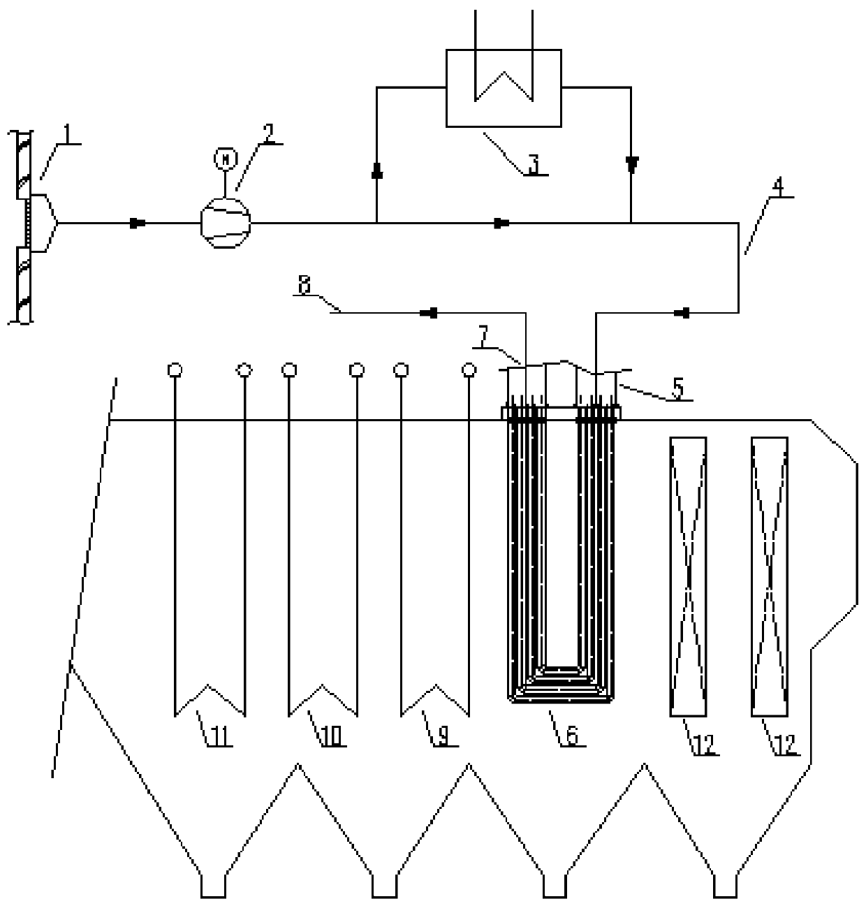
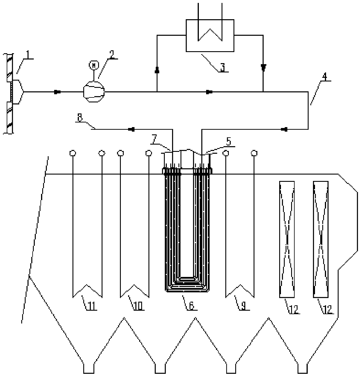
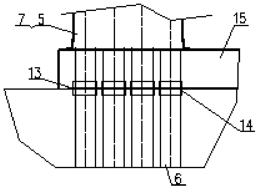
[0027] like figure 1 , figure 2 As shown, taking the horizontal boiler as an example, the process flow is: the primary air is sucked by the primary fan 2 from the air suction port 1 above the garbage bin, heated by the steam air preheater 3, and fed into the flue gas air through the primary air duct inlet 4 The inlet header 5 of the preheater is heated to a certain temperature by the high temperature flue gas through the heat exchange tube 6, and then sent out from the outlet header 7 of the flue gas air preheater, and finally sent to the incinerator through the outlet 8 of the primary air duct. in the wind room.

[0028] In principle, different calorific values ​​of waste require different temperatur...


PUM


Abstract

The invention relates to a smoke air preheater for increasing the garbage incineration primary combustion supporting air temperature. A primary draught fan sucking primary air is included and connected with an air suction port above a garbage bin, pipeline communication with a steam air preheater is conducted, the primary air sequentially passes through a primary air pipe inlet and a smoke air preheater inlet header, and passes through a heat exchange pipe, communicates with a smoke air preheater outlet header and finally communicates with various primary air chambers of an incinerator througha primary air pipe outlet. After primary combustion supporting air is heated to 180-200 DEG C through the steam air preheater, the primary combustion supporting air is conveyed to the smoke air preheater at the front end of an economizer through an air pipe for continuous air temperature increasing, and the smoke air preheater can be placed between a medium-temperature overheater and a low-temperature overheater so that the primary air temperature increasing requirement can be met. By means of the smoke air preheater, high-temperature corrosion caused to the smoke air preheater from high-temperature smoke sections of 600 DEG C or above can be avoided, and meanwhile it is guaranteed that the primary air temperature can be heated to the high temperature section.

Description

technical field [0001] The invention relates to a combustion air system for waste incineration, which is a device applied to a waste incinerator to heat the temperature of primary combustion-supporting air, also known as a primary air device. Background technique [0002] Air preheater is a device used to heat combustion air for combustion, usually including: primary air preheater, secondary air preheater, etc. [0003] In traditional coal-fired power plants, the air preheater adopts flue gas-air heat exchange, and is usually placed at the end of the flue at the boiler tail, that is, the rear end of the economizer, and usually one or more groups of air preheaters are placed. However, in a waste incineration power plant, due to the diversity and complexity of waste components, the instability of combustion conditions, and the large amount of impurities and particulate matter contained in the flue gas generated by waste incineration, the air preheating of waste incineration po...

Claims


Application Information

Patent Timeline
IPC IPC(8): F23G5/44F23G5/46F23L15/04
CPCF23G5/44F23G5/46F23G2206/10F23L15/04Y02E20/34
Inventor 黄洁卿中华徐俊焦学军白力杜海亮曹阳彭小龙赵玉明姚琴
Owner SHANGHAI SUS ENVIRONMENT
Learn More