
Differential pressure air speed detection and control device

A wind speed detection and control device technology, which is applied in the direction of detecting fluid flow by measuring pressure difference, manufacturing cigarettes, transportation and packaging, etc., can solve the problem that cannot solve the influence of the conveying speed of shredded tobacco, and does not detect the wind speed of the air supply and dust removal branch pipe of the cigarette machine, shredded tobacco Problems such as retention, to achieve the effect of maintaining high-precision detection for long-term operation, ensuring effective operation rate and reliability, and reducing resistance loss

Inactive Publication Date: 2010-10-20
扬州市天宝自动化工程有限公司
View PDF1 Cites 12 Cited by
  • Summary
  • Abstract
  • Description
  • Claims
  • Application Information

AI Technical Summary

Problems solved by technology

[0003] The above technical solution uses a split wedge flowmeter to detect the wind speed of the shredded tobacco conveying pipe, but does not detect the wind speed of the dust removal branch pipe of the cigarette machine, which cannot solve the influence of air leakage on the shredded tobacco conveying speed of the shredded cigarette machine and the system pipeline.
The wedge-shaped throttling piece of the split wedge flowmeter is installed in the shredded tobacco conveying pipe, which occupies more than half of the cross-sectional area of ​​the pipe. Since the shredded tobacco moves irregularly in the pipe when the air is blown, the shredded tobacco directly collides with the wedge-shaped throttling piece, causing the shredded tobacco to break, which is easy to produce Tobacco retention, adhesion and blockage
Its main disadvantage is that the resistance loss of the fluid passing through the wedge-shaped throttling parts is large, and the high flow accuracy needs to be calibrated after actual flow, and the wedge-shaped flowmeter needs to be calibrated regularly

Method used


Image

  • Differential pressure air speed detection and control device
  • Differential pressure air speed detection and control device
  • Differential pressure air speed detection and control device

Examples


Embodiment Construction

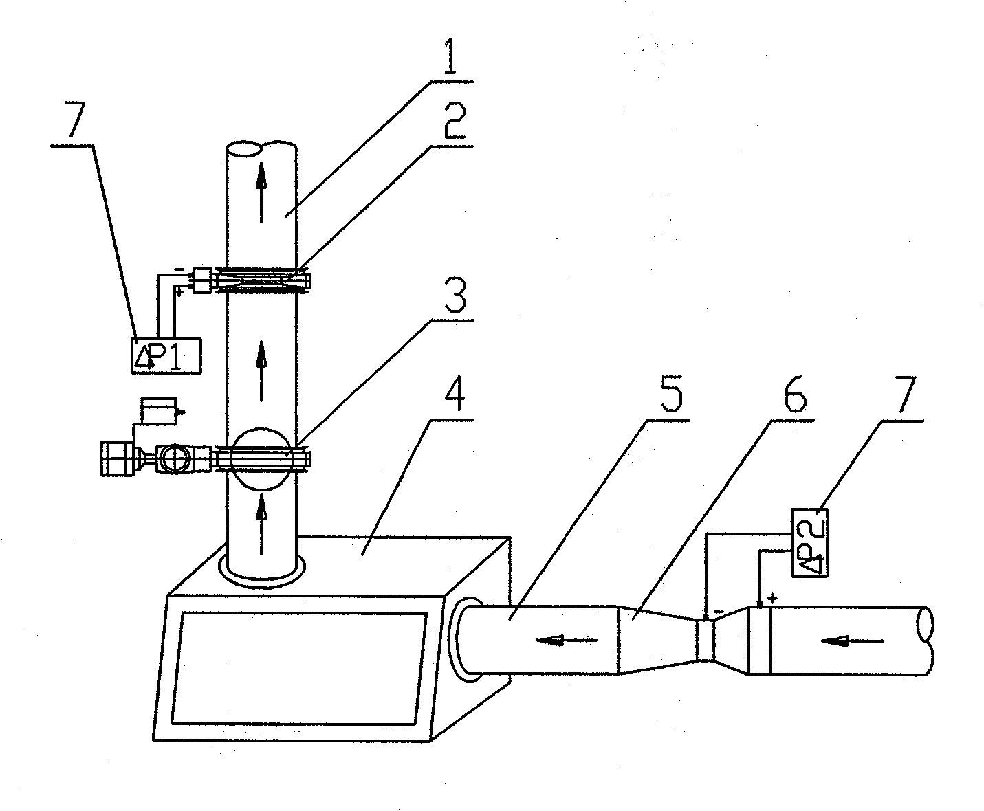
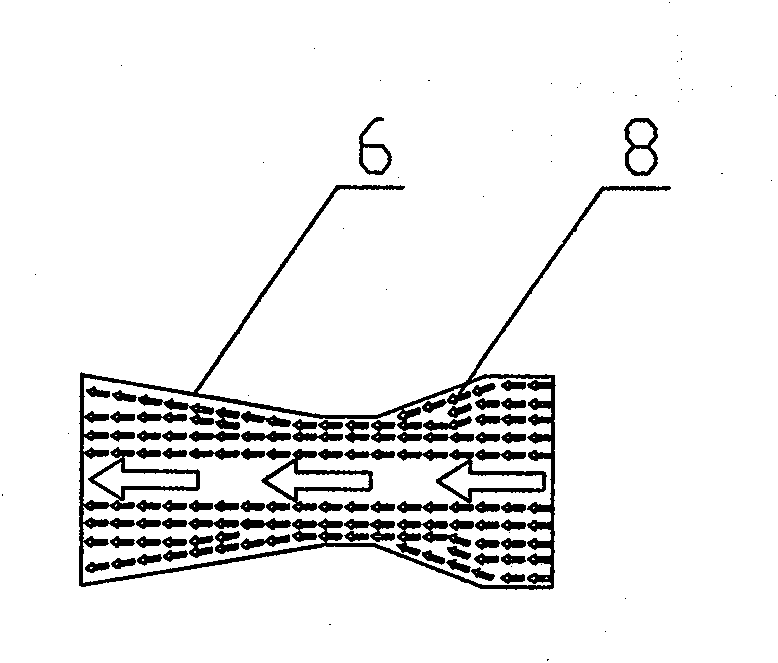
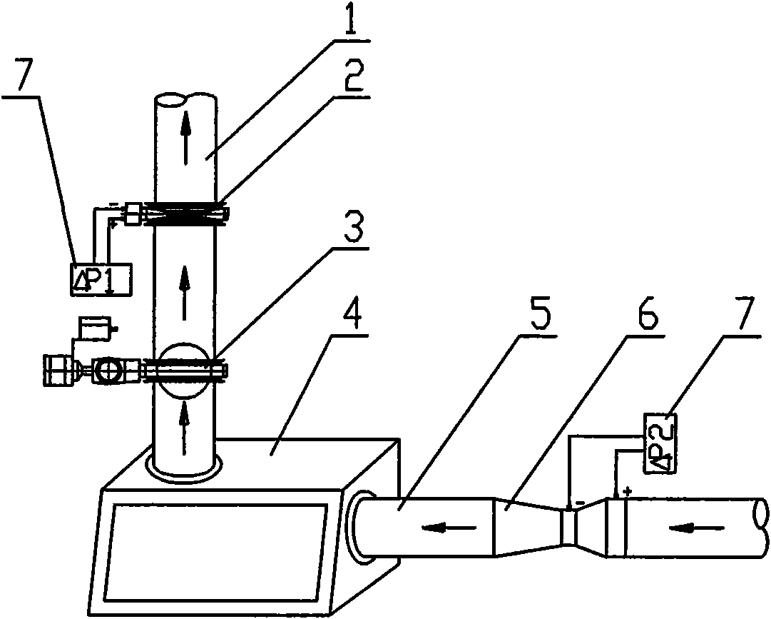
[0013] A differential pressure wind speed detection and control device, including an air supply dust removal branch pipe 1, an electric (pneumatic) regulating butterfly valve 3, a cigarette machine silk collecting box 4, a shredded tobacco conveying pipeline 5, and a differential pressure flowmeter, a differential pressure flowmeter It is a split-type venturi flowmeter, which consists of a split-type venturi flowmeter pressure measuring component 6 and a differential pressure sensor 7; it also includes a split-type orifice flowmeter, which consists of a split-type orifice flowmeter The pressure measuring assembly 2 of the split orifice flowmeter is composed of a differential pressure sensor 7 . In actual operation, when the cigarette machine wire collection box 4 needs shredded tobacco, its own pneumatic switch butterfly valve is opened, and the system negative pressure wind draws shredded tobacco from the pneumatic wire distribution machine into the shredded tobacco conveying ...


PUM


Abstract

The invention relates to a differential pressure air speed detection and control device, which comprises an air-conveying de-dusting branch pipe, an electric (pneumatic) adjustment butterfly valve, a cut tobacco collecting box of a cigarette making machine, a cut tobacco conveying pipeline and a differential pressure flowmeter, and is characterized by also comprising a split type orifice flowmeter arranged on the air-conveying de-dusting branch pipe, wherein the differential pressure flowmeter is a split type venturi flowmeter and is arranged on the cut tobacco conveying pipeline, and the speed measuring pipe diameter of the venturi flowmeter gradually becomes small and then gradually becomes large. The invention eliminates the phenomena of cut tobacco retention, adhesion and blockage, is more suitable for detection of cut tobacco material flow in the cut tobacco conveying pipeline, and can maintain long-term operation of high-precision detection to ensure the effective operating ratio and reliability of a system.

Description

technical field [0001] The invention relates to a detection and control device for the wind speed and flow in the shredded tobacco conveying pipeline and the air-conveyed dust removal branch pipe, in particular to a differential pressure wind speed detection and control device. Background technique [0002] With the requirement of continuous cigarette production, the pneumatic conveying system has become an indispensable device for the production line of domestic and foreign cigarette technology. Practice has proved that pneumatic conveying can achieve loosening, impurity removal, cooling, dust removal and other technological purposes during the conveying process. Due to the pneumatic conveying, the shredded tobacco runs in a closed pipeline, and the tobacco dust will not be distributed into the workshop, which will damage the working environment of the workshop. However, if the design and use of the entire pneumatic conveying system are improper, such as high conveying win...

Claims


Application Information

Patent Timeline
Patent Type & Authority Applications(China)
IPC IPC(8): A24C5/39B65G53/58G01F1/34
Inventor 乔维宝房广军薛玉明
Owner 扬州市天宝自动化工程有限公司
Learn More