Efficient punching device for machines

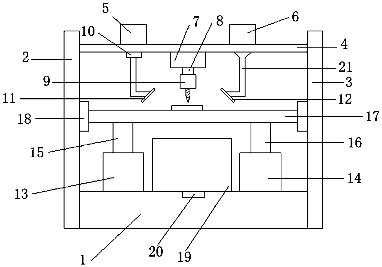
A punching device, high-efficiency technology, applied in cleaning methods and appliances, cleaning methods using gas flow, metal processing, etc., can solve the problem of clamping fixtures for workpieces to be processed, debris that cannot be centrally processed, and continuous work, etc. problems, to achieve the effect of easy removal, easy collection, and easy automatic clamping

Inactive Publication Date: 2020-02-21
户玉珠
View PDF7 Cites 7 Cited by
  • Summary
  • Abstract
  • Description
  • Claims
  • Application Information

AI Technical Summary

Problems solved by technology

[0002] With the further development of processing technology, consumers' requirements for the processing quality of mechanical technician products are also constantly improving. Now there are more and more types of processing equipment in technology, and the application fields are becoming more and more extensive. Drilling machines are mechanical parts. One of the processing machines often used in the processing process, a punching machine refers to a machine that uses a tool that is harder and sharper than the target to leave a cylindrical hole or hole on the target by means of rotary cutting or rotary extrusion It is a general term for equipment, but the traditional drilling machine needs to use a small drill bit to drill a preliminary deep hole, and then use a large drill bit to ream the hole. It is very troublesome to replace the drill bit in the middle, and it cannot work continuously at the same time, and the production efficiency is low. At the same time, the debris generated during the drilling process cannot be treated centrally, and the fixture for clamping the workpiece to be processed is also troublesome

Method used


Image

  • Efficient punching device for machines
  • Efficient punching device for machines
  • Efficient punching device for machines

Examples


Embodiment Construction

[0021] The present invention will be further described below in conjunction with specific embodiments, wherein, the accompanying drawings are only for exemplary illustrations, and what is shown is only a schematic diagram, rather than a physical map, and cannot be understood as a limitation to this patent. In order to better illustrate the present invention Specific embodiments, some parts in the drawings will be omitted, enlarged or reduced, and do not represent the size of the actual product. For those skilled in the art, it is understandable that some known structures and their descriptions in the drawings may be omitted. Based on The specific implementation modes in the present invention and all other specific implementation modes obtained by persons of ordinary skill in the art without making creative efforts all belong to the protection scope of the present invention.

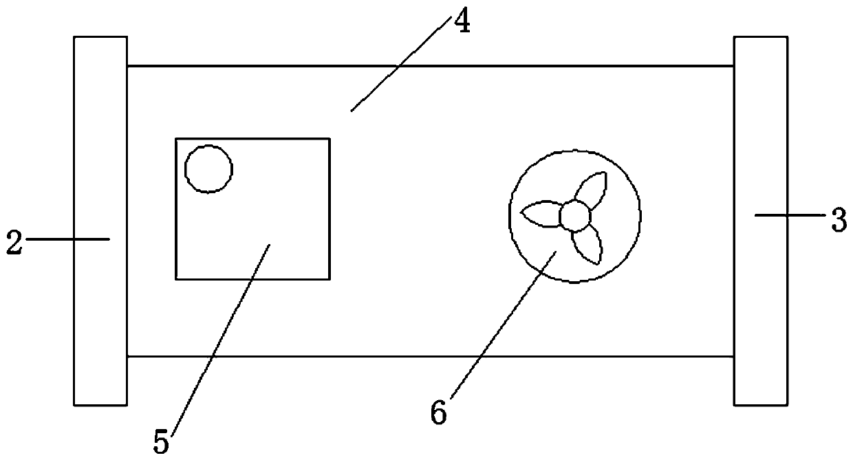
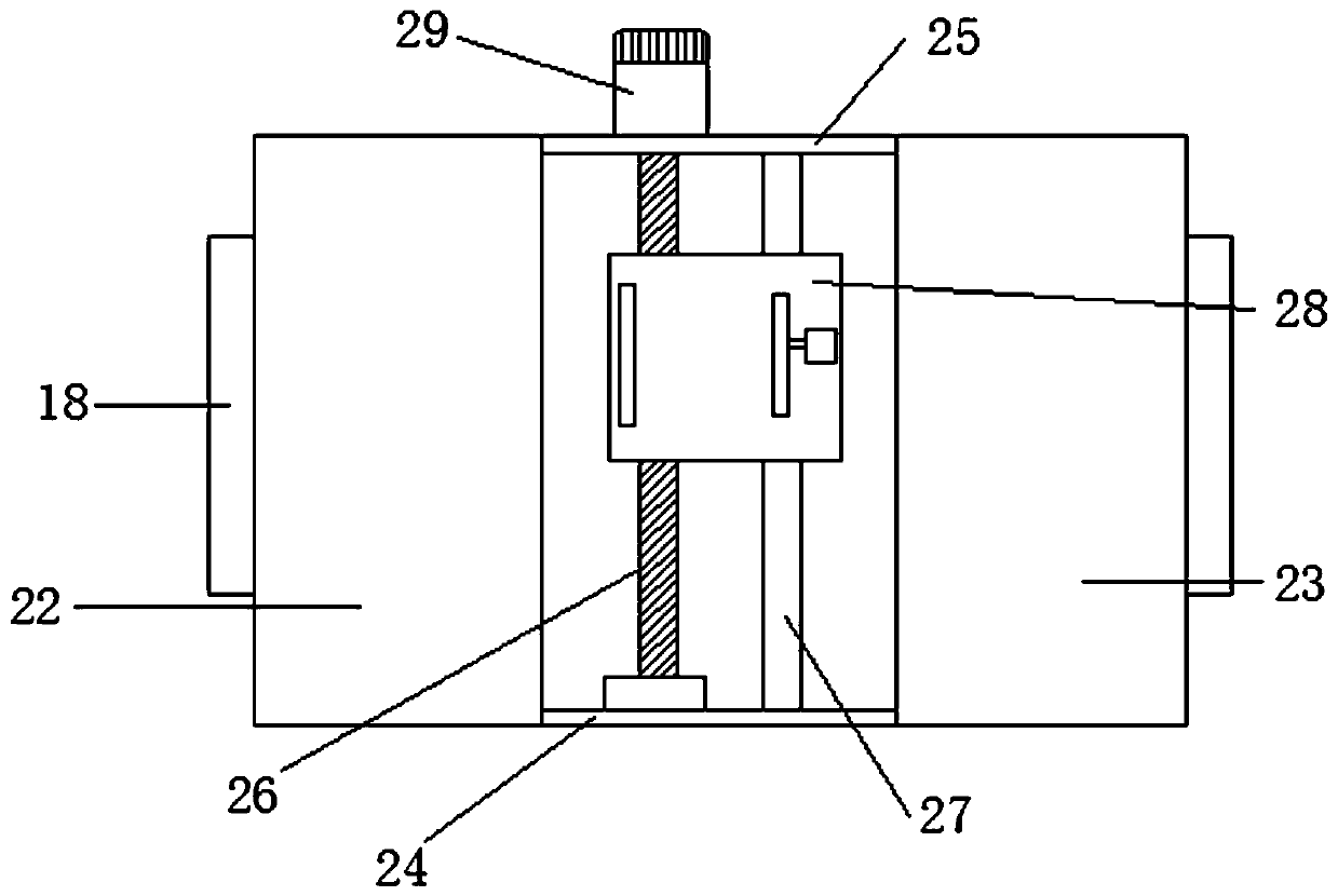
[0022] Such as Figure 1-4As shown, a high-efficiency punching device for machinery includes a base 1,...


PUM


Abstract

The invention relates to an efficient punching device for machines. The efficient punching device comprises a base, a first supporting plate is fixedly connected to the left end of the base, a secondsupporting plate is fixedly connected to the right end of the base, and a top plate is fixedly connected between the first supporting plate and the second supporting plate. A water tank and a draughtfan are fixedly connected to the top of the top plate, the draught fan is arranged at the right side of the water tank, and a first hydraulic cylinder is fixedly connected to the bottom of the top plate. A first motor is connected to the bottom of the first hydraulic cylinder through a first hydraulic telescopic rod, a drill is fixedly connected to the output end of the first motor, a water pump is connected to the bottom of the water tank through a water pipe, a sprayer is connected to the bottom of the water pump through a water pipe, the draught fan penetrates through the top plate to be connected with an air feeding pipe, and an air feeding plate is fixedly connected to the bottom end of the air feeding pipe. Convenience is brought to workpiece clamping and positioning, automatic clamping in the punching process is facilitated, and the safety and efficiency are higher; meanwhile, punched portions are conveniently cooled, and chippings generated in the punching process are conveniently collected.

Description

technical field [0001] The invention relates to a high-efficiency punching device for machinery, which belongs to the field of mechanical equipment. Background technique [0002] With the further development of processing technology, consumers' requirements for the processing quality of mechanical technician products are also constantly improving. Now there are more and more types of processing equipment in technology, and the application fields are becoming more and more extensive. Drilling machines are mechanical parts. One of the processing machines often used in the processing process, a punching machine refers to a machine that uses a tool that is harder and sharper than the target to leave a cylindrical hole or hole on the target by means of rotary cutting or rotary extrusion It is a general term for equipment, but the traditional drilling machine needs to use a small drill bit to drill a preliminary deep hole, and then use a large drill bit to ream the hole. It is ver...

Claims


Application Information

Patent Timeline
Patent Type & Authority Applications(China)
IPC IPC(8): B26F1/16B26D5/04B26D5/08B26D7/02B26D7/08B26D7/18B08B5/02
CPCB08B5/02B26D5/04B26D5/086B26D7/02B26D7/08B26D7/1845B26F1/16
Inventor 户玉珠
Owner 户玉珠
Why Eureka
Try Eureka