
Charging supporting structure

A technology of supporting structure and charging, which is applied in the directions of jet propulsion, rocket engine, machine/engine, etc., can solve the problems of affecting the charging profile of the front-end combustion chamber, performance deviating from the design value, damage to the interlayer structure, etc. To achieve the effect of charging stability, beneficial to the overall design, and effective charging

Active Publication Date: 2020-02-14
SHANGHAI XINLI POWER EQUIP RES INST
View PDF5 Cites 2 Cited by
  • Summary
  • Abstract
  • Description
  • Claims
  • Application Information

AI Technical Summary

Problems solved by technology

[0003] The existing engine structure is generally a structure with front and rear closures. When designing a pulse engine with a soft interlayer, since the interlayer is a soft insulation layer, if it cannot be effectively supported during charging, the entire interlayer will be deformed, affecting The charge profile of the front section of the combustion chamber causes the performance to deviate from the design value, and in severe cases, even causes damage to the interlayer structure

Method used


Image

  • Charging supporting structure
  • Charging supporting structure
  • Charging supporting structure

Examples


Embodiment 1

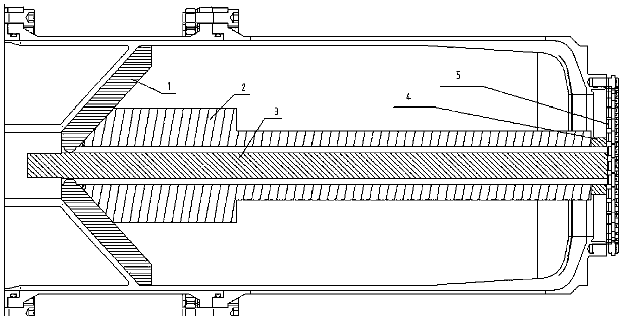
[0031] A charge support structure, including a mandrel 1, a support rod 2, an inner cylinder 3, a fastening device 4, and a support plate 5;

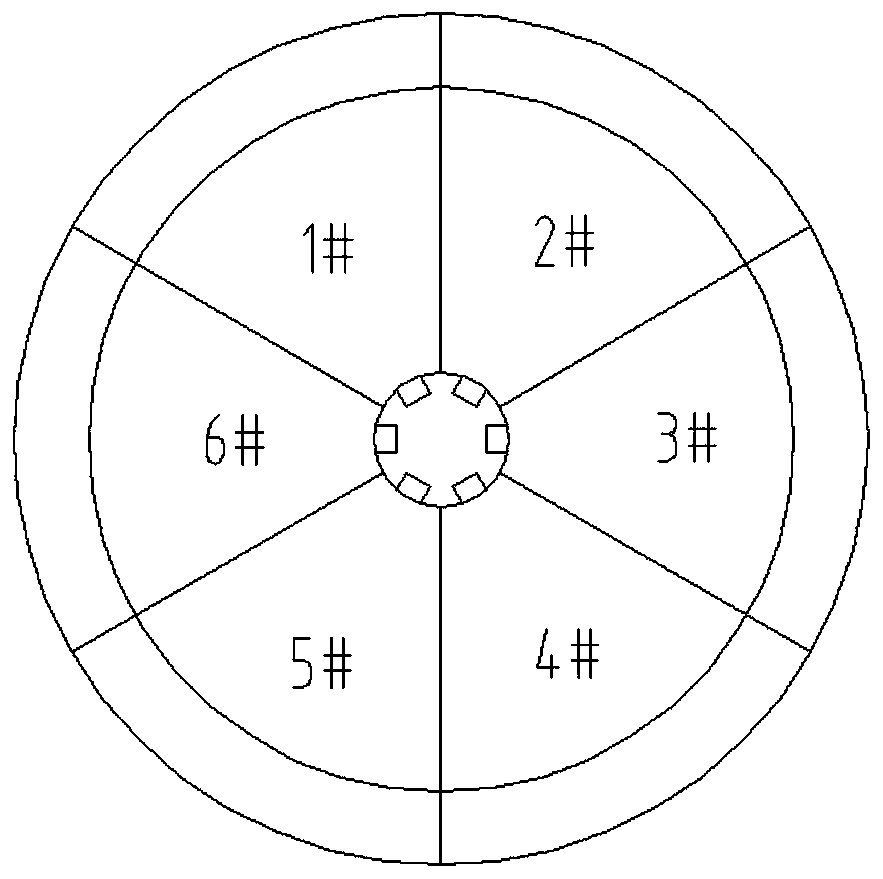
[0032] The mandrel 1 includes a plurality of fan rings, and the plurality of fan rings form a ring shape, the mandrel 1 is used to support the soft compartment of the external engine; the support rod 2 is used to support the mandrel 1; The inner cylinder 3 is used for positioning and guiding the mandrel 1 after being connected with the external structure; the fastening device 4 is used for connecting the support rod 2 and the inner cylinder 3; the support plate 5 is connected with the external engine After the head end is connected, support force is provided to the inner cylinder 3 and the support rod 2 at the same time.

[0033] The surface of the inner cylinder 3 is provided with a guide groove, and each of the fan rings is provided with a slide groove, and the guide groove is matched with the slide groove.

[0034] The cross-section...

Embodiment 2

[0044] A charge support structure, the main technical proposal is: the charge support structure includes a mandrel 1, an inner cylinder 3, a support rod 2, a support plate 5, and a fastening device 4. In this embodiment, the fastening device 4 adopts a reinforcement nut After the mandrel 1 splits into the designated position through the petal groove (guide groove) of the inner cylinder 3, it is stretched by the support rod 2 to form a tapered whole to support the soft interlayer. The reinforcement nut is fixed, the inner cylinder 3 is fixed by the support plate 5, and the support plate 5 is fastened by screws to realize the initial design state of the compartment when the two-pulse charging is completed; after the front pulse combustion chamber completes the solidification of the charge, remove the support plate 5 and the reinforcement nut, pull out the support rod 2, you can hook out the mandrel 1, then remove the inner cylinder 3, and finally connect the wing column rear rod ...


PUM


Abstract

The invention discloses a charging supporting structure. The structure comprises a core mold (1), a supporting rod (2), an inner cylinder (3), a fastening device (4) and a supporting plate (5). The core mold (1) comprises multiple fan rings, a circular ring shape is formed by the fan rings, the core mold is used for supporting a soft interlayer of an outer engine, the supporting rod (2) is used for supporting the core mold (1), the inner cylinder (3) is connected with an outer structure to position and guide the core mold (1), the fastening device (4) is used for connecting the supporting rod(2) and the inner cylinder (3), and the supporting plate (5) is connected with the seal head end of the outer engine and meanwhile provides supporting force for the inner cylinder (3) and the supporting rod (2). Through the structure, association of the opening diameter and the whole size of the supporting structure does not need to be considered, the opening diameter size of the engine is reduced, charging can be more effective, the higher filling ratio is achieved, and the whole design of the engine is facilitated.

Description

technical field [0001] The invention relates to a charge support structure, in particular to a charge support structure for a soft interlayer solid impulse motor. Background technique [0002] Because the solid pulse engine can realize multiple ignitions and release thrust intermittently, it can effectively improve energy utilization efficiency and improve missile performance. The pulse engine can realize the combustion of the charge in the pulse combustion chamber in sequence through the control of the ignition interval according to the command of the missile, and provide intermittent power for the missile. Compared with conventional solid motors, it has many advantages such as effectively realizing energy management, increasing missile range, expanding the interception combat airspace, improving missile speed characteristics, and flexibly adapting to combat tasks. [0003] The existing engine structure is generally a structure with front and rear closures. When designing ...

Claims


Application Information

Patent Timeline
Patent Type & Authority Applications(China)
IPC IPC(8): F02K9/24
CPCF02K9/24
Inventor 潘科玮蔡迪汤玉林牛禄王志新陈坚张斌刘晓晨沈飞荣
Owner SHANGHAI XINLI POWER EQUIP RES INST
Learn More