Rotary driving type steel wire rope winding device

A winding device and rotary drive technology, which is applied in the direction of transportation and packaging, conveying filamentous materials, thin material processing, etc., can solve the problems of increasing the tension and looseness of the wire rope, and achieve the effect of convenient installation, disassembly and replacement of parts

Pending Publication Date: 2020-02-14
江苏艾可森钢绳有限公司
View PDF0 Cites 0 Cited by
  • Summary
  • Abstract
  • Description
  • Claims
  • Application Information

AI Technical Summary

Problems solved by technology

The steel wire rope is first twisted into strands by multi-layer steel wires, and then twisted into a helical rope by a certain number of strands with the rope core as the center; The diameter of the steel wire rope is generally relatively large. When the wire rope is wound on the reel, it will often appear loose, and it is impossible to adjust the telescopic relaxation of the reel. Therefore, it is necessary to develop a telescopic relaxation adjustment to achieve increase. Rotary-driven wire rope winding device for wire rope tension

Method used


Image

  • Rotary driving type steel wire rope winding device
  • Rotary driving type steel wire rope winding device
  • Rotary driving type steel wire rope winding device

Examples


Embodiment Construction

[0021] The content of the present invention will be further described in detail below in conjunction with the accompanying drawings.

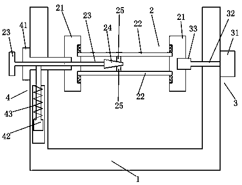
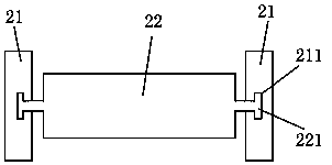
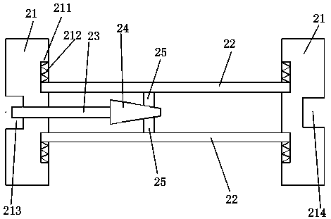
[0022] Such as Figures 1 to 5 As shown, a rotary-driven wire rope rewinding device includes a bracket 1, a rewinding mechanism 2, and a driving mechanism 3; the rewinding mechanism 2 is installed above the middle of the bracket 1; the rewinding mechanism 2 includes a limit Positioning plate 21, floating plate 22, driving screw 23, conical driving block 24, driven wedge block 25; said limiting plate 21 is provided with two, and two limiting plates 21 are respectively arranged in parallel on the left and right sides; Two floating plates 22 are provided, and the two floating plates 22 are installed up and down between the two limiting plates 21; The floating plate 22 is an arc-shaped structure protruding outward; the driving mechanism 3 is installed on one side of the bracket 1, and the driving mechanism 3 is connected to a limit plate 21 and co...


PUM


Abstract

The invention discloses a rotary driving type steel wire rope winding device which comprises a bracket, a winding mechanism and a driving mechanism. The winding mechanism includes limiting plates, floating plates, a driving screw, a tapered driving block and driven wedge blocks. By means of the rotary driving type steel wire rope winding device, the traditional winding structure of a cylinder is changed, the driving screw is connected to the other side of the bracket in threaded rotating and penetrating manners, one end of the driving screw penetrates through the other limiting plate to extendto the position between the two floating plates, the end, extending into the position between the two floating plates, of the driving screw is provided with the tapered driving block, and the tapereddriving block abuts against the two driven wedge blocks; and when rotationally and transversely moving, the tapered driving block can abut against the two driven wedge blocks to move longitudinally,so that the two floating plates relatively float between the two limiting plates, the distance between the two floating plates can be adjusted, and the effect of adjusting the tightening force of a steel wire rope is achieved.

Description

technical field [0001] The invention relates to a rotary-driven wire rope rewinding device. Background technique [0002] The steel wire rope is a spiral steel wire bundle twisted together with steel wires whose mechanical properties and geometric dimensions meet the requirements according to certain rules. The steel wire rope is composed of steel wire, rope core and lubricating grease. The steel wire rope is first twisted into strands by multi-layer steel wires, and then twisted into a helical rope by a certain number of strands with the rope core as the center; The diameter of the steel wire rope is generally relatively large. When the wire rope is wound on the reel, it will often appear loose, and it is impossible to adjust the telescopic relaxation of the reel. Therefore, it is necessary to develop a telescopic relaxation adjustment to achieve increase. Rotation-driven wire rope take-up device for wire rope tension. Contents of the invention [0003] Aiming at the de...

Claims


Application Information

Patent Timeline
Patent Type & Authority Applications(China)
IPC IPC(8): B65H54/10B65H54/74
CPCB65H54/10B65H54/74B65H2701/36
Inventor 陆伟春周亚萍薛丰斌顾宏亮严兴龙
Owner 江苏艾可森钢绳有限公司
Why Eureka
Try Eureka