
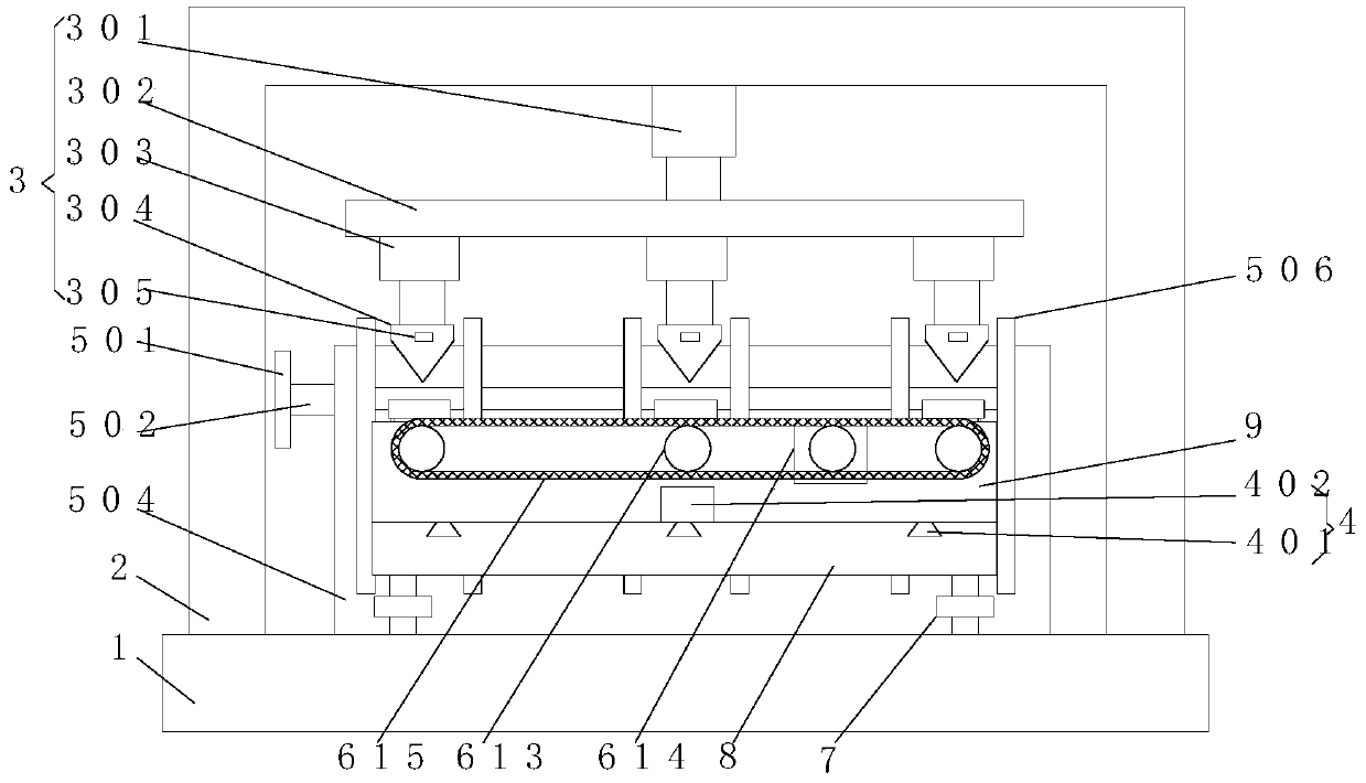
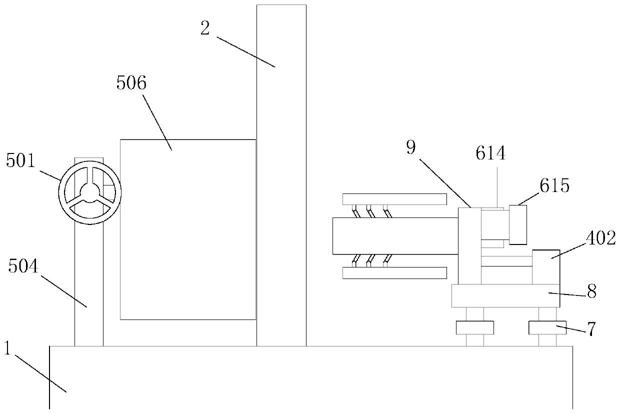
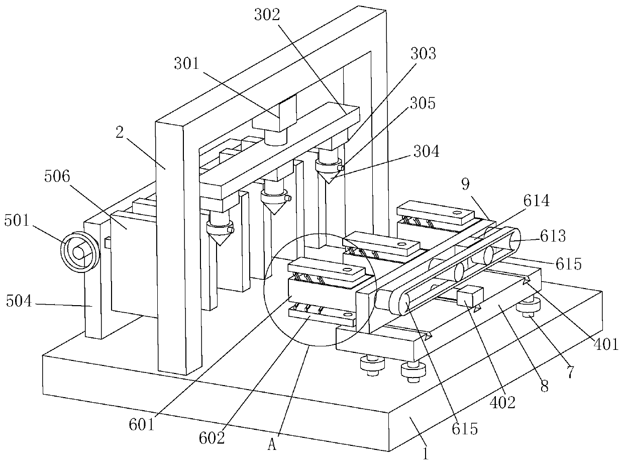
Production and processing equipment for manufacturing U-shaped hanging ring of electric power fitting

A technology for electric power fittings and processing equipment, which is applied to metal processing equipment, manufacturing tools, metal processing machinery parts, etc. It can solve the problems of difficulty in realizing the two side walls of U-shaped hanging rings, lack of support devices, and slow drilling speed, etc., to achieve Reduce deformation, improve accuracy, and improve work efficiency

Active Publication Date: 2020-02-14
江苏东恒光电有限公司
View PDF7 Cites 6 Cited by
  • Summary
  • Abstract
  • Description
  • Claims
  • Application Information

AI Technical Summary

Problems solved by technology

[0007] In view of the problems in the prior art, the purpose of the present invention is to provide a U-shaped hanging ring manufacturing and processing equipment for electric power fittings, which solves the problem that the existing U-shaped hanging ring processing machine can only drill one hanging ring at a time Processing makes the drilling speed slow, and also solves the problem of the existing U-shaped hanging ring processing machine. When drilling the top of the U-shaped hanging ring two side walls, due to the lack of supporting devices in the middle of the U-shaped hanging ring, the drill bit is opposite to the The extrusion of the side wall makes the side wall bend during the processing of the hanging ring, and it is difficult to realize that the round holes punched on the two side walls of the U-shaped hanging ring are coaxial.

Method used


Image

  • Production and processing equipment for manufacturing U-shaped hanging ring of electric power fitting
  • Production and processing equipment for manufacturing U-shaped hanging ring of electric power fitting
  • Production and processing equipment for manufacturing U-shaped hanging ring of electric power fitting

Examples


Embodiment Construction

[0036] The embodiments of the present invention will be described in detail below with reference to the accompanying drawings, but the present invention can be implemented in many different ways defined and covered by the claims.

[0037] In order to make the technical means, creative features, goals and effects achieved by the present invention easy to understand, the present invention will be further described below in conjunction with specific illustrations.

[0038] It should be noted that when an element is referred to as being "fixed" to another element, it may be on the other element or may be an intervening element. When an element is referred to as being "connected to" another element, it can be directly connected to the other element or intervening elements may also be present. The terms "vertical", "horizontal", "left", "right" and similar expressions are used herein for the purpose of illustration only and do not represent the only embodiment.

[0039] see Figur...


PUM


Abstract

The invention discloses production and processing equipment for manufacturing a U-shaped hanging ring of electric power fittings, and relates to the technical field of mechanical manufacturing process. The production and processing equipment comprises a base and a second clamping device, wherein the base is of a working table structure horizontally placed on the ground, a machine frame is arrangedat the top end of the base, the machine frame is of a U-shaped structure with a downward opening, a drilling device is arranged on the inner wall of the top end of the machine frame, the drilling device comprises an open hole drill, a first pressing device and a bidirectional screw rod are arranged at the top end of the base, and a horizontally placed bottom plate is fixed at the top end of the bidirectional screw rod. According to the production and processing equipment, a plurality of fixing plates are arranged, each fixing plate is provided with a movable clamping plate and a rotating rod,a second motor can simultaneously drive the plurality of rotating rods to rotate at the same time, and the movable clamping plates clamp the plurality of U-shaped hanging rings in the vertical direction, so that the plurality of U-shaped hanging rings are machined at one time, and the working efficiency is improved.

Description

technical field [0001] The invention relates to the technical field of mechanical manufacturing and processing, in particular to a production and processing equipment for U-shaped hanging rings of electric fittings. Background technique [0002] The U-shaped hanging ring is forged from round steel and has a wide range of uses. It can be used alone or in two strings. The common U-shaped hanging rings include U-shaped and UL-shaped. At present, the U-shaped hanging rings are The market consumption is large, and the national consumption is tens of millions of tons. It is a product that needs to be mass-produced, because the shape of the U-shaped hanging ring is relatively special, and it is inconvenient to process. High, involving material mechanics, mechanical manufacturing, forging technology, stamping technology, every change in production practice has to go through a lot of practical operations to prove its correctness. [0003] The existing patent No. CN201810969548.5 rel...

Claims


Application Information

Patent Timeline
Patent Type & Authority Applications(China)
IPC IPC(8): B23B41/00B23B47/22B23Q3/06B23Q3/08
CPCB23B41/00B23Q3/062B23Q3/082B23Q5/34
Inventor 潘学勇刘云华
Owner 江苏东恒光电有限公司
Learn More