Safe type aluminum alloy cutting equipment

A cutting equipment, aluminum alloy technology, applied in metal processing equipment, metal processing, metal processing machinery parts, etc., can solve the problems of difficult aluminum alloy multi-angle cutting, affecting aluminum alloy safe cutting, aluminum alloy sliding or tilting, etc. Achieve the effect of improving safe cutting operations

Active Publication Date: 2020-02-11
新沂天源节能材料有限公司
View PDF6 Cites 2 Cited by
  • Summary
  • Abstract
  • Description
  • Claims
  • Application Information

AI Technical Summary

Problems solved by technology

[0006] In order to make up for the deficiencies of the existing technology, the invention proposes a safe aluminum alloy cutting equipment. The invention is mainly used to solve the problem that most of the existing aluminum alloys are cut by the operator manually operating the cutting machine to cut the aluminum alloy. , this kind of cutting method, when cutting strip-shaped aluminum alloys of different widths and lengths, if the aluminum alloys are not fixed firmly, it is easy to cause the aluminum alloys to slip or tilt during cutting, which will affect the safe cutting of aluminum alloys; At the same time, when cutting aluminum alloys obliquely, the existing equipment is difficult to perform multi-angle cutting operations on aluminum alloys.

Method used


Image

  • Safe type aluminum alloy cutting equipment
  • Safe type aluminum alloy cutting equipment
  • Safe type aluminum alloy cutting equipment

Examples


Embodiment approach

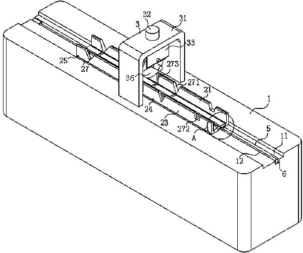
[0029] As an embodiment of the present invention, the bottom end of the guide chute 11 is provided with a limit groove 12; the bottom end of the positioning support plate 21 is provided with a screw rod 5 slider 4, and the screw rod 5 slider 4 is located In the limit groove 12; the screw mandrel 5 slider 4 is connected with the screw mandrel 5 for rotation, and the end of the screw mandrel 5 is connected with the rotating motor 6; the other side wall of the guide chute 11 is provided with a limit guide slot, and a guide cylinder 24 and a guide rod 25 are slidably installed in the limit guide slot; during work, when the fixed and clamped aluminum alloy to be cut needs to be moved to the bottom of the cutting piece 36, the controller controls the rotation of the motor 6 , the rotating motor 6 will drive the screw rod 5 slider 4 to slide in the limit groove 12 through the screw rod 5, and the sliding of the screw rod 5 slider 4 will drive the positioning support plate 21 and the c...


PUM


Abstract

The invention belongs to the technical field of aluminum alloy cutting equipment and particularly provides safe type aluminum alloy cutting equipment. The safe type aluminum alloy cutting equipment comprises a cutting platform; the upper end face of a positioning support plate is provided with a supporting block; the sidewall of the positioning support plate is provided with a sliding chute; a sliding support plate is slidably arranged on a guide sliding chute by virtue of a guide cylinder; the positioning support plate and the sliding support plate are both slidably arranged inside the guidesliding chute; a push cylinder is installed at the upper end of a supporting frame; the telescopic end of the push cylinder is connected with a U-shaped bracket after penetrating through the supporting frame; the inside of the U-shaped bracket is hinged with a mounting cover by virtue of a hinging block; a cutting blade is rotationally installed inside the mounting cover by virtue of a rotating column; a cutting motor is installed at the sidewall of the mounting cover; the output end of the cutting motor is connected with the rotating column; a limiting cylinder is installed at the two sides of the U-shaped bracket; and the telescopic end of the limiting cylinder is hinged to the mounting cover by virtue of the hinging block, thereby preventing the influences on safe and stable cutting ofa cutting worker to aluminum alloy as the aluminum alloy is relatively short when an operator cuts the aluminum alloy.

Description

technical field [0001] The invention belongs to the technical field of aluminum alloy cutting equipment, in particular to a safe aluminum alloy cutting equipment. Background technique [0002] Aluminum alloy profiles are the most widely used non-ferrous metal structural materials in the industry, and are widely used in aviation, aerospace, automobiles, machinery manufacturing, ships, construction, and decoration. And the chemical industry has been widely used. With the rapid development of science and technology and industrial economy in recent years, the demand for welded structural parts of aluminum alloys is increasing, and the research on the weldability of aluminum alloys is also in-depth. The wide application of aluminum alloy has promoted the development of aluminum alloy welding technology, and the development of welding technology has expanded the application field of aluminum alloy, so the welding technology of aluminum alloy is becoming one of the hot spots of re...

Claims


Application Information

Patent Timeline
IPC IPC(8): B23D79/00B23Q3/06B23Q7/00
CPCB23D79/00B23Q3/062B23Q7/00
Inventor 付才
Owner 新沂天源节能材料有限公司
Why Eureka
Try Eureka