
Noise prediction method for automobile exhaust system

A technology of automobile exhaust system and prediction method, which is applied in the field of automobile interior noise measurement, can solve the problems of low prediction efficiency, long time required, and low calculation efficiency of finite element model, so as to improve the prediction speed of interior noise and reduce the The effect of calculation volume

Active Publication Date: 2020-02-07
SAIC-GM-WULING AUTOMOBILE CO LTD
View PDF6 Cites 8 Cited by
  • Summary
  • Abstract
  • Description
  • Claims
  • Application Information

AI Technical Summary

Problems solved by technology

Due to the complex structure of the vehicle, in order to ensure the calculation accuracy, the acoustic-vibration coupling model of the acoustic cavity and the vehicle body usually contains a very high number of meshes and degrees of freedom, so a calculation takes a long time and the prediction efficiency is extremely low; in addition, the vehicle The operating conditions are changeable, and in-vehicle noise prediction results of multiple working conditions are required in actual projects
Existing vehicle interior noise prediction methods based on the acoustic-vibration coupling model of the interior acoustic cavity and the vehicle body face the bottleneck of low calculation efficiency of the finite element model

Method used


Image

  • Noise prediction method for automobile exhaust system
  • Noise prediction method for automobile exhaust system
  • Noise prediction method for automobile exhaust system

Examples


Embodiment Construction

[0023] The present invention will be described in further detail below in conjunction with the accompanying drawings.

[0024] The flow chart of a noise prediction method for a vehicle exhaust system in an embodiment of the present invention is as follows figure 1 As shown, the method includes:

[0025] S101, pre-establishing an acoustic-vibration coupling finite element calculation model between the acoustic cavity in the vehicle and the vehicle body;

[0026] This step is used to establish the acoustic-vibration coupling finite element calculation model between the acoustic cavity in the vehicle and the vehicle body. The body structure mainly includes the body in white and its accessories, such as doors, windows, floors, connectors, etc.; the interior acoustic cavity is a closed internal air cavity surrounded by the body structure. Before building the model, it is necessary to prepare a complete CAD model of the car body. The model usually contains rich structural details...


PUM


Abstract

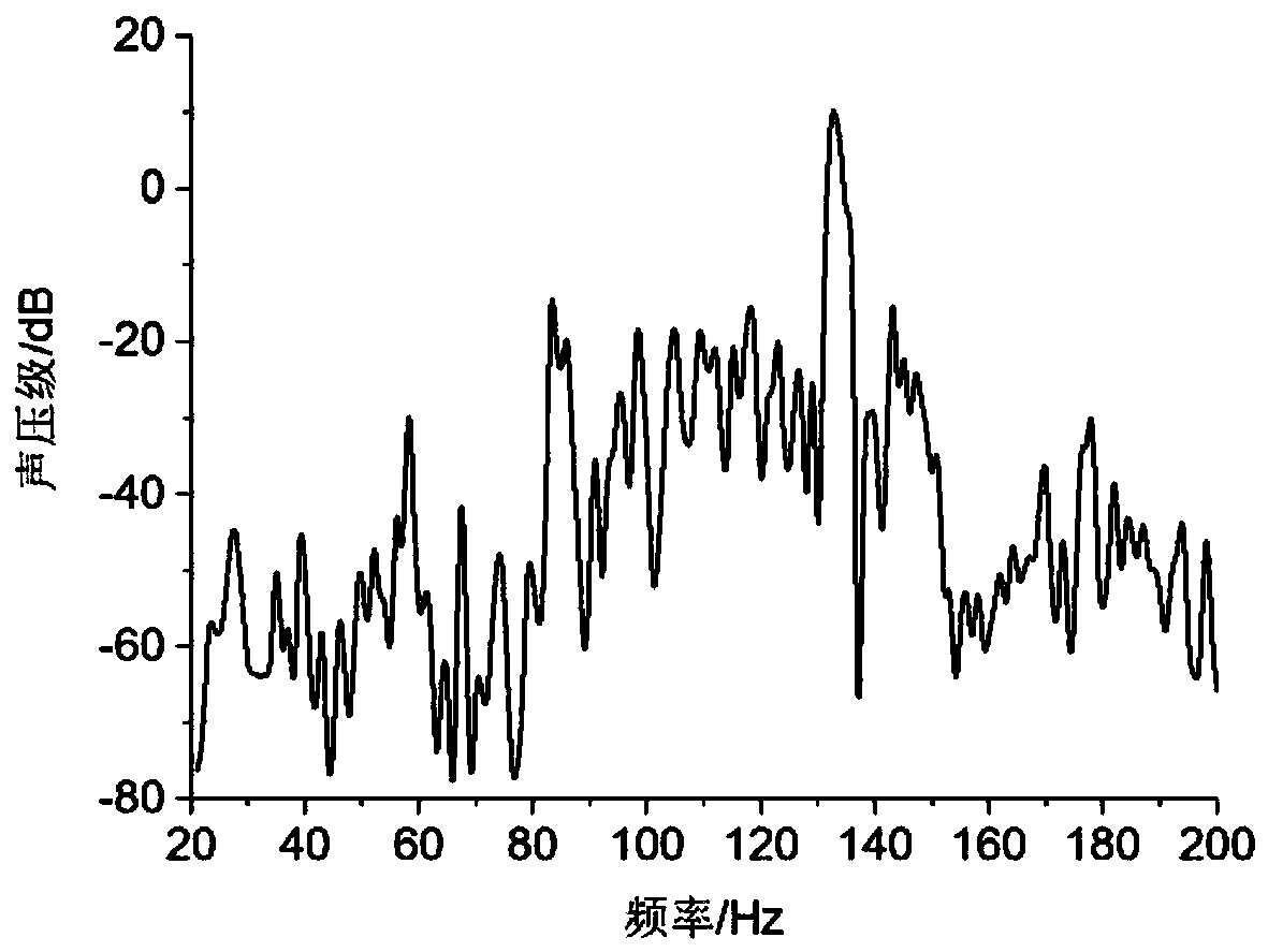
The invention discloses a noise prediction method for an automobile exhaust system. The method comprises: establishing a sound-vibration coupling finite element calculation model between an in-vehiclesound cavity and a vehicle body in advance; pre-calculating an exhaust system lifting hook vibration transmission force-in-vehicle target point noise sound pressure transmission function in a frequency domain under different operation conditions, and storing the function into a database; pre-calculating an exhaust system lifting hook suspension point vibration displacement-lifting hook vibrationtransmission force transfer function in a frequency domain under different operation conditions, and storing the function into a database; establishing a kinetic finite element calculation model of the exhaust system, and calculating the vibration displacement at the suspension point of the lifting hook; and multiplying the vibration displacement by a vibration transmission force-in-vehicle targetpoint noise sound pressure transmission function and a vibration displacement-lifting hook vibration transmission force transmission function in a database to predict the noise sound pressure of thein-vehicle target point. Because the two transfer functions do not need to be calculated during noise prediction, the calculated amount is greatly reduced, and the prediction speed of the noise in thevehicle is improved.

Description

technical field [0001] The invention belongs to the technical field of automobile interior noise measurement, and in particular relates to a method for predicting noise caused by vibration of an automobile exhaust system. Background technique [0002] The noise inside the car is one of the important factors affecting the ride comfort. High noise can not only damage the physical and mental health of the occupants, but also cause rapid fatigue of the driver, which poses a great threat to the driving safety of the car. With the improvement of road conditions and the application of vehicle vibration ride comfort research results, vehicle interior noise plays an increasingly important role in evaluating vehicle ride comfort. At present, the research aimed at reducing the noise level in the car, improving the acoustic environment in the car, and improving the comfort of the car has become one of the research hotspots in the automotive field, and the rapid and accurate prediction ...

Claims


Application Information

Patent Timeline
IPC IPC(8): G06F30/23G06F30/15G06F119/14
CPCY02T90/00
Inventor 王田修邓国勇徐炳桦王晓蒙刘杰昌李明瑞米永振
Owner SAIC-GM-WULING AUTOMOBILE CO LTD
Learn More