
Tungsten production waste water convection purification device

A purification device and a technology for producing wastewater, which is applied in metallurgical wastewater treatment, water pollutants, water/sewage treatment, etc. It can solve problems such as incomplete purification work, mutual purification that cannot achieve the expected effect, and a sudden drop in the falling speed of wastewater.

Inactive Publication Date: 2020-02-07
郭慧珍
View PDF7 Cites 3 Cited by
  • Summary
  • Abstract
  • Description
  • Claims
  • Application Information

AI Technical Summary

Problems solved by technology

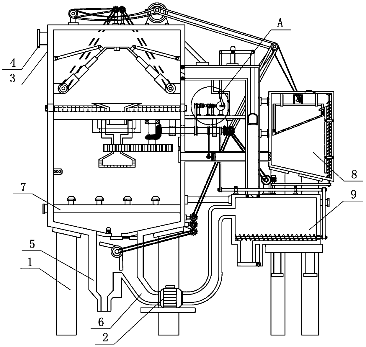
[0005] In order to overcome the problem that the existing waste water purification device handles waste water in tungsten production, it generally needs to use sulfur dioxide in the waste gas, spray strong alkaline waste water from above in a container, and blow in waste gas containing sulfur dioxide from below to make the two Meet in the air, neutralize and purify each other, but in fact, because the waste water falls extremely fast and the speed of the exhaust gas drops sharply after leaving the blower, the mutual purification effect cannot achieve the expected effect; moreover, because the gas is extremely mobile, the reaction is difficult to control, If the purification is performed only once, the waste water will not fully react with the sulfur dioxide when it falls from the spray port to the bottom of the container. Ninety percent of sulfur dioxide produced in industry will also be accompanied by nitrogen dioxide. Nitrogen dioxide is also a highly toxic gas. It also needs to be purified according to the nature of nitrogen dioxide, but it is difficult to complete it with existing equipment The shortcoming of this work, the technical problem to be solved in the present invention is to provide a kind of tungsten production wastewater convection purification device

Method used


Image

  • Tungsten production waste water convection purification device
  • Tungsten production waste water convection purification device
  • Tungsten production waste water convection purification device

Examples


Embodiment

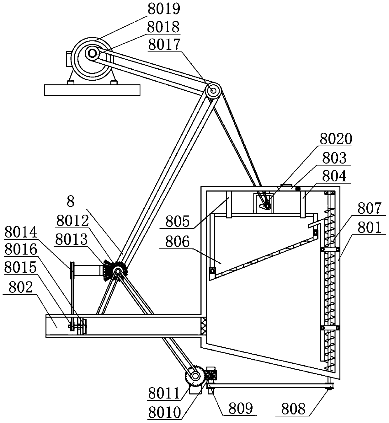
[0025] A convection purification device for tungsten production wastewater, such as Figure 1-5 As shown, it includes an underframe 1, a water pump 2, a high-efficiency atomization neutralization device 3, a waste water inlet 4, a purified water outlet 5, a circulation inlet 6, an exhaust gas injection port 7, a nitrogen dioxide purification device 8 and a well type purification device 9; A water pump 2 is installed at the bottom of the front end of the chassis 1; an efficient atomization neutralization device 3 is installed on the left side of the top of the chassis 1; the left end of the water pump 2 is connected to the circulation inlet 6, and the top of the circulation inlet 6 is connected to the high efficiency atomization neutralization device 3 The right end of the water pump 2 is connected to the well type purification device 9 through a pipeline, and the left top of the well type purification device 9 is connected to the high-efficiency atomization neutralization devic...


PUM


Abstract

The invention relates to a waste water treatment device, in particular to a tungsten production waste water convection purification device. The invention aims to provide the tungsten production wastewater convection purification device. The tungsten production waste water convection purification device comprises a high-efficiency atomizing and neutralizing device, a nitrogen dioxide purificationdevice and a well type purification device; and the high-efficiency atomizing and neutralizing device is arranged on the left side of the top end of a bottom frame. The problem that sulfur dioxide inwaste gas generally needs to be utilized as well as in a container, alkaline waste water is sprayed from top and waste gas containing the sulfur dioxide is blown from bottom when an existing waste water purification device treats waste water of tungsten production. The flowing speed of the waste gas and the waste water is controlled, the purification effect is improved, the waste water which cannot be purified completely is recovered and sulfate ions in the waste water are settled, so that the fact that the dissolving capacity of the sulfur dioxide is not reduced during secondary purificationis guaranteed; and sodium peroxide solid is thrown circularly and the nitrogen dioxide is completely absorbed, so that the aim of completely purifying the waste gas and the waste water is finally fulfilled.

Description

technical field [0001] The invention relates to a treatment device, in particular to a convection purification device for tungsten production wastewater. Background technique [0002] When industrially producing tungsten, it is necessary to go through a step called "alkali leaching". As the name implies, it uses alkaline liquid to dissolve the tungsten-containing compound in the ore, separate it from other unnecessary mixed impurities, and then remove the tungsten-containing compound in the solution. The compound separates out, after which the lye is no longer needed. In order to prevent environmental pollution, lye is generally discharged after treatment. If it is discharged without treatment, it will directly increase the pH value of the water and destroy the living environment of aquatic organisms. The most basic and most vigorous aquatic Plants cannot survive, which directly destroys the repair ability of the water body, which will cause the water body to no longer repa...

Claims


Application Information

Patent Timeline
IPC IPC(8): C02F9/04B01D53/14B01D53/18C02F101/10C02F103/16
CPCB01D53/1493B01D53/18B01D2257/40C02F1/5236C02F1/66C02F2101/101C02F2103/16Y02A50/20
Inventor 郭慧珍
Owner 郭慧珍
Learn More