
Automatic packaging tape winding system

An adhesive tape and automatic technology, applied in the direction of packaging/bundling items, packaging, wrapping items, etc., can solve the problems of dust and oil on the surface of the workpiece, poor quality of packaging products, and low degree of automation, saving manpower and material resources and reducing the weight of the body. , the effect of high degree of automation

Inactive Publication Date: 2020-02-07
青岛新伟嘉音自动化包装有限公司
View PDF0 Cites 14 Cited by
  • Summary
  • Abstract
  • Description
  • Claims
  • Application Information

AI Technical Summary

Problems solved by technology

[0004] The main purpose of the present invention is to provide an automatic tape winding system to solve the problem of low automation in the tape winding and packaging process in the prior art, poor packaging environment, dust and oil on the surface of the workpiece, which makes the tape sticking not firm, and low packaging efficiency. The problem of poor quality packaging products

Method used


Image

  • Automatic packaging tape winding system
  • Automatic packaging tape winding system
  • Automatic packaging tape winding system

Examples


Embodiment 1

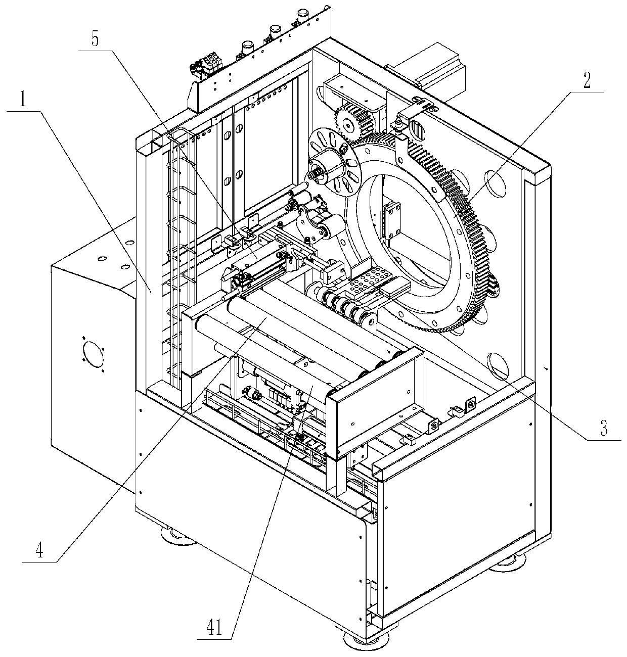
[0036] Such as Figure 1-7 As shown, an automatic tape winding system described in this embodiment includes a frame 1, a rotating tape sticking device 2, a tape smoothing and cutting device 3, a workpiece supporting device 4, a tape pressing device 5 and a workpiece pressing device 6.

[0037] The rotary taping device is installed on the front end of the frame, including a drive assembly, a slewing support 21 rotatably connected to the frame, and a tape applicator connected to the slewing support; the drive assembly is connected to the slewing support, and the drive assembly drives the slewing support to rotate. There is a through hole in the middle of the slewing support, and there is a gap corresponding to the position of the through hole on the frame for placing the workpiece.

[0038] The drive assembly includes a servo motor 27 and a transmission gear 22. The slewing support is circular, and the outer surface of the slewing support has transmission teeth that match the t...

Embodiment 2

[0055] The difference between this embodiment and Embodiment 1 is that there is a baffle 24 at the end of the adhesive tape fixing sleeve near the slewing support, and a detection hole 241 is provided on the baffle, and the detection holes are arranged in a ring on the baffle, and the baffle can limit the tape The fixed position of the roll, with a detection device on the frame, the detection signal of the detection device passes through the detection hole to detect the remaining thickness of the tape roll, which is convenient for timely replacement of the tape roll; the detection device corresponds to the initial position of the tape fixed sleeve, and the detection process is The prior art will not be described in detail here.

Embodiment 3

[0057] The difference between this embodiment and Embodiment 1 and Embodiment 2 is that the adhesive tape fixing sleeve is provided with a movable groove 231, a movable block 232 is installed on the movable groove, a spring is installed between the movable block and the movable groove, and the movable block moves towards the movable groove. Internal activities, the tape roll is covered on the tape fixing sleeve, and then under the action of the spring restoring force, the movable block resets, and the tape roll is clamped on the tape fixing sleeve to prevent the tape roll from sliding.


PUM


Abstract

The invention relates to the field of product packaging equipment, in particular to an automatic packaging tape winding system. The system comprises a rack, a rotating packaging tape sticking device,a packaging tape flattening cutting device, a workpiece supporting device, a packaging tape pressing device and a workpiece pressing device. The rotating packaging tape sticking device is mounted on the front end of the rack, and comprises a driving assembly, a rotation support and a packaging tape sticking device, the packaging tape flattening cutting device is mounted on the lower end of the rack and comprises a packaging tape cutting assembly, an optical shaft, and a flattening air cylinder, the workpiece supporting device comprises multiple rollers mounted on the rack, the packaging tape pressing device is arranged on the side face of the rack and comprises a first telescopic part and a second telescopic part, and the workpiece pressing device is located on the back side of the rack and comprises a pressing air cylinder and a pressing block. The system is high in automation degree, and the problems in the prior art, the packaging tap winding and packaging process is complex, due tothe poor packaging environment, dust and oil dirt on the surface of a workpiece are many, sticking of the packaging tap is not firm, packaging efficiency is low, and the packaging product quality ispoor are solved.

Description

technical field [0001] The invention relates to the field of product packaging equipment, in particular to an automatic tape winding system. Background technique [0002] At present, the outer packaging of products generally needs to be wrapped and sealed with adhesive tape. The existing process of wrapping adhesive tape on the outer packaging is generally manual winding and packaging by workers. For outer packaging with large shapes and sizes, the winding process is cumbersome and needs to be automated. The degree is low, the work efficiency is low, and the product packaging quality is low. [0003] The traditional tape winding machine cannot produce a whole assembly line, there are many processes, the operation is troublesome, the overall equipment occupies a large space, and the operation is complicated, which reduces the production speed and increases the production cost. Generally, there will be a lot of dust or oil on the surface. Just wrapping the tape on the surface...

Claims


Application Information

Patent Timeline
IPC IPC(8): B65B13/18B65B11/02B65H35/07
CPCB65B11/02B65B13/18B65H35/0033
Inventor 王洪涛孙凯
Owner 青岛新伟嘉音自动化包装有限公司
Learn More