
Deep grouting device and method

A grouting device and deep technology, applied in protection devices, buildings, infrastructure projects, etc., can solve the problems of treating the symptoms but not the root cause, inconvenient for the spread of grouting, and inability to achieve large-flow grouting.

Active Publication Date: 2021-10-15
东方雨虹智能装备有限责任公司
View PDF0 Cites 0 Cited by
  • Summary
  • Abstract
  • Description
  • Claims
  • Application Information

AI Technical Summary

Problems solved by technology

[0005] The diameter of the central through hole of the grease nipple used in this kind of grouting head is generally about 1.5mm, which cannot realize large-flow grouting; There is not enough space, which is not convenient for the spread of grouting material; the grouting head cannot go deep into the grouting hole to a sufficient depth, because the space of the grouting hole is too large, resulting in excessive grouting material filling; because of this The grouting head can only be grouted in the leakage gap on the concrete surface, so it is necessary to place multiple grouting heads at a certain distance, and because the check valve is at the fracture, after the grouting is completed, it is necessary to wait for the grout to solidify before cutting the rod body, otherwise As the check valve is cut off, there will be a phenomenon of grout backflow, resulting in poor sealing of the grouting hole, and there is a hidden danger of leakage
[0006] Therefore, it is expected to develop a deep grouting device and method, which can make the grouting head go deep into the grouting hole, change the current engineering status of the existing shallow grouting that treats the symptoms but not the root cause, and solves the leakage problem from the source of the leakage water without the need Cut off to avoid backflow of grouting fluid

Method used


Image

  • Deep grouting device and method
  • Deep grouting device and method
  • Deep grouting device and method

Examples


Embodiment

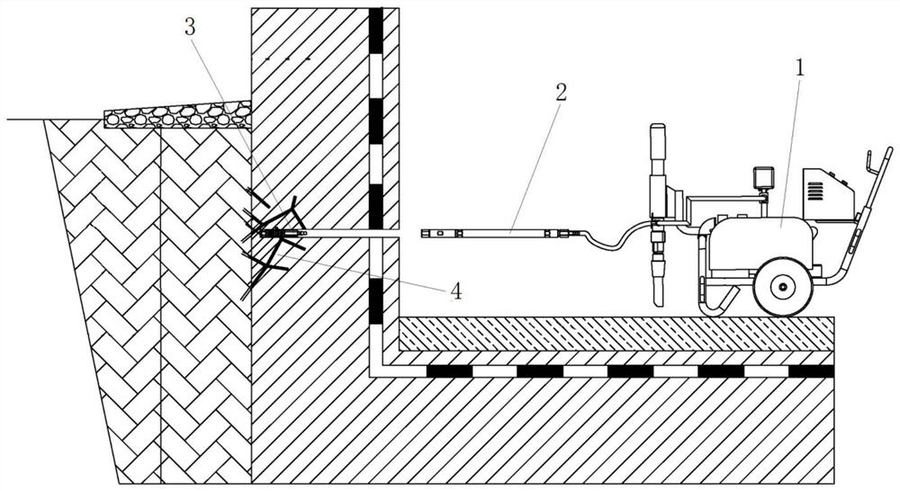
[0090] figure 1 A schematic structural diagram of a deep layer grouting device according to this embodiment is shown; figure 2 A schematic structural diagram of the adapter according to this embodiment is shown; image 3 A schematic diagram of the internal structure of the adapter according to this embodiment is shown; Figure 4 A schematic structural diagram of a grouting head according to this embodiment is shown; Figure 5 A schematic diagram of the internal structure of the grouting head according to this embodiment is shown.

[0091] Such as Figure 1 to Figure 5 As shown, the deep grouting device includes:

[0092] Grouting machine 1;

[0093] The connector 2, the connector 2 includes a connecting pipe 5 and a quick-connect female head, one end of the connecting pipe 5 is connected to the grouting machine, and the quick-connect female head is arranged at the other end of the connecting pipe 5;

[0094] Wherein, the quick-connect female head includes a quick-connect ...


PUM


Abstract

The invention discloses a deep grouting device and method, comprising: a grouting machine; a connector including a connecting pipe and a quick-connect female head, one end of the connecting pipe is connected to the grouting machine, and the quick-connecting female head is arranged on the connecting pipe The other end of the barge; the grouting head includes a grouting pipe, a quick connector, a filling structure and a check valve. One end of the grouting pipe is provided with a grouting nozzle, and the quick connector is arranged at the other end of the grouting pipe It is connected with the outer wall of the grouting pipe through threads, and the filling structure is sleeved on the grouting pipe and between the grouting nozzle and the quick-connect male. The grouting pipe can be inserted into the quick-connect of the connector through the quick-connect male. In the female head, the quick-connect female head can drive the quick-connect male head to rotate to squeeze the filling structure and expand the outer diameter of the filling structure to fill the gap between the outer wall of the grouting pipe and the hole wall of the grouting hole. The check valve is used to prevent the grouting fluid from flowing back from the grouting pipe to the connector. In order to realize deep grouting, change the current situation that shallow grouting treats the symptoms but not the root cause, and at the same time simplifies the construction process and avoids the backflow of grout.

Description

technical field [0001] The invention belongs to the technical field of waterproofing, and more specifically relates to a deep grouting device and method. Background technique [0002] With the continuous development of cities and the continuous improvement of residents' living standards, the number of motor vehicles is increasing, and parking spaces are becoming increasingly scarce. There is an obvious shortage of parking spaces in most cities, and the construction of underground parking lots can partially alleviate the demand for parking spaces in cities. However, there are almost all leaks in large underground garages, and it is difficult to completely treat them. Leakage from settlement joints in the basement, water leakage from structural cracks, water leakage from post-casting belts, and water leakage from wall pipes have emerged in endlessly. The water seepage problem in the basement not only affects the normal use of the basement, but also poses a safety hazard to t...

Claims


Application Information

Patent Timeline
Patent Type & Authority Patents(China)
IPC IPC(8): E02D19/06E02D19/12E02D31/02E02D15/00
CPCE02D15/00E02D19/06E02D19/12E02D31/02
Inventor 林海侠王新马鑫马力吕继峰
Owner 东方雨虹智能装备有限责任公司
Learn More