Lifting platform used for truck loading

A technology for lifting platforms and platforms, which is applied in the direction of lifting frames and lifting devices, which can solve the problems of low stability and achieve the effect of improving stability and avoiding damage

Active Publication Date: 2020-02-04
重庆市佳禾家具制造有限公司
View PDF5 Cites 4 Cited by
  • Summary
  • Abstract
  • Description
  • Claims
  • Application Information

AI Technical Summary

Problems solved by technology

[0004] The present invention intends to provide a lifting platform for loading vehicles to solve the problem that the current lifting platform only supports the platform through hydraulic cylinders and has low stability

Method used


Image

  • Lifting platform used for truck loading
  • Lifting platform used for truck loading

Examples


Embodiment 1

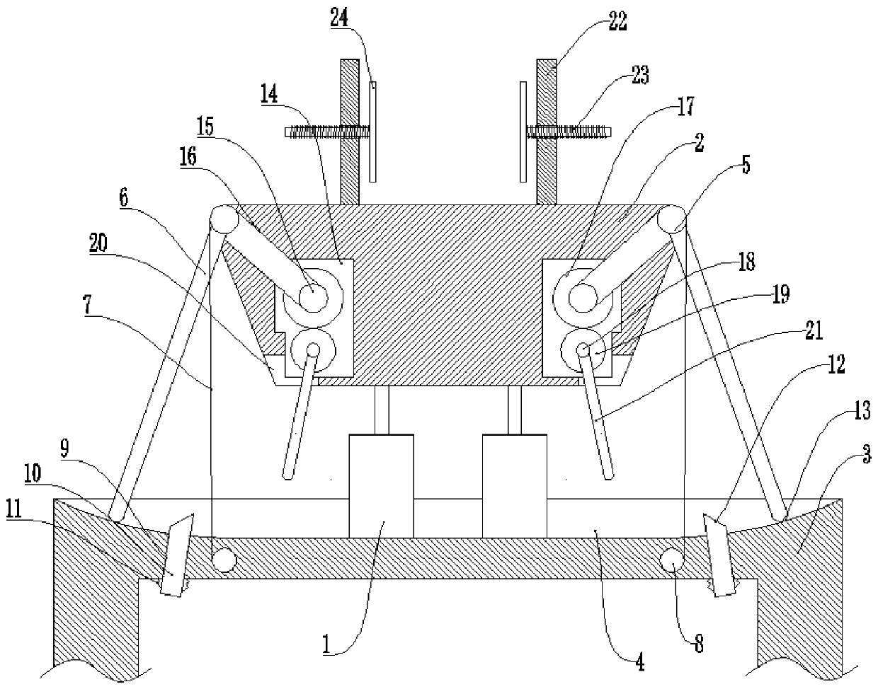
[0027] Basic as attached figure 1 Shown: the lifting platform for loading vehicles, including hydraulic cylinder 1 and platform 2, the output shaft of hydraulic cylinder 1 is fixedly connected to the bottom of platform 2. It also includes a fixed platform 3, a groove 4 is formed on the bottom of the fixed platform 3, and the hydraulic cylinder 1 is fixed in the middle of the groove 4.

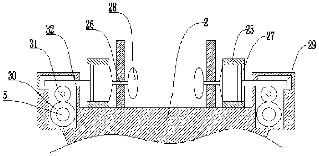
[0028] Both sides of the platform 2 are provided with a supporting mechanism for the lifting of the platform 2. The supporting mechanism includes a rotating shaft 5 connected in rotation with the platform 2 and a swing arm 6 fixed on the arc surface of the rotating shaft 5. The rotating shaft 5 and the platform 2 are fixed. A torsion spring is connected, and the rotating shaft 5 is fixedly connected with a steel wire rope 7 wound on the rotating shaft 5; the groove 4 is arc-shaped, and the swing arm 6 is located in the groove 4, and the swing track of the swing arm 6 is consistent with the radi...


PUM


Abstract

The invention relates to the technical field of platform ascending and descending and discloses a lifting platform used for truck loading. The lifting platform comprises a hydraulic cylinder and a platform. An output shaft of the hydraulic cylinder is fixedly connected with the platform. The lifting platform further comprises a fixing table, a groove is formed in the bottom of the fixing table, and the hydraulic cylinder is fixedly connected to the groove. Supporting mechanisms used for ascending and descending of the platform are arranged on the two sides of the platform. According to the scheme, the problem that a current lifting platform is supported only through a hydraulic cylinder, and stability is low is mainly solved.

Description

technical field [0001] The invention relates to the technical field of platform lifting. Background technique [0002] When carrying out vertical transportation in logistics systems such as factories and automatic warehouses, various plane conveying equipment are often installed on the lifting platform as connection devices for different height conveying lines. It is generally driven by hydraulic pressure, so it is called hydraulic lifting platform. In addition to transporting goods at different heights, it is widely used in high-altitude installation, maintenance and other operations. [0003] At present, it is necessary to place loading vehicles on the platform, drive the platform up through hydraulic cylinders, and then drive the loading vehicles to move to the goods collection place, then collect or pile up the goods on the loading vehicles, and finally drive the platform down through the hydraulic cylinders, thereby realizing the goods. Transportation; in actual use, ...

Claims


Application Information

Patent Timeline
IPC IPC(8): B66F7/16B66F7/28
CPCB66F7/16B66F7/28B66F2700/12
Inventor 唐静
Owner 重庆市佳禾家具制造有限公司
Why Eureka
Try Eureka