
Mould change structure for injection moulding machine

A technology for injection molding machines and fixed molds, which is applied in the field of mold change structure for injection molding machine processing, can solve the problems of difficult centralized management of molds and slow replacement speed, etc., so as to avoid maintenance difficulties, improve the efficiency of mold change, and have high practical value Effect

Inactive Publication Date: 2020-02-04
上海金通塑料模具制品有限公司
View PDF10 Cites 5 Cited by
  • Summary
  • Abstract
  • Description
  • Claims
  • Application Information

AI Technical Summary

Problems solved by technology

In the process of using the injection molding machine, different molds can be replaced to realize the production of different products, but the existing mold replacement of the injection molding machine is mainly done manually, and the mold of the injection molding machine is very heavy, resulting in not only slow replacement speed, but also The physical exertion of workers is also serious, and the mold cannot be placed too far away from the injection molding machine, which makes it difficult to centrally manage the mold

Method used


Image

  • Mould change structure for injection moulding machine
  • Mould change structure for injection moulding machine
  • Mould change structure for injection moulding machine

Examples


Embodiment Construction

[0022] The following will clearly and completely describe the technical solutions in the embodiments of the present invention with reference to the accompanying drawings in the embodiments of the present invention. Obviously, the described embodiments are only some, not all, embodiments of the present invention. Based on the technical solutions in the present invention, all other embodiments obtained by persons of ordinary skill in the art without making creative efforts belong to the protection scope of the present invention.

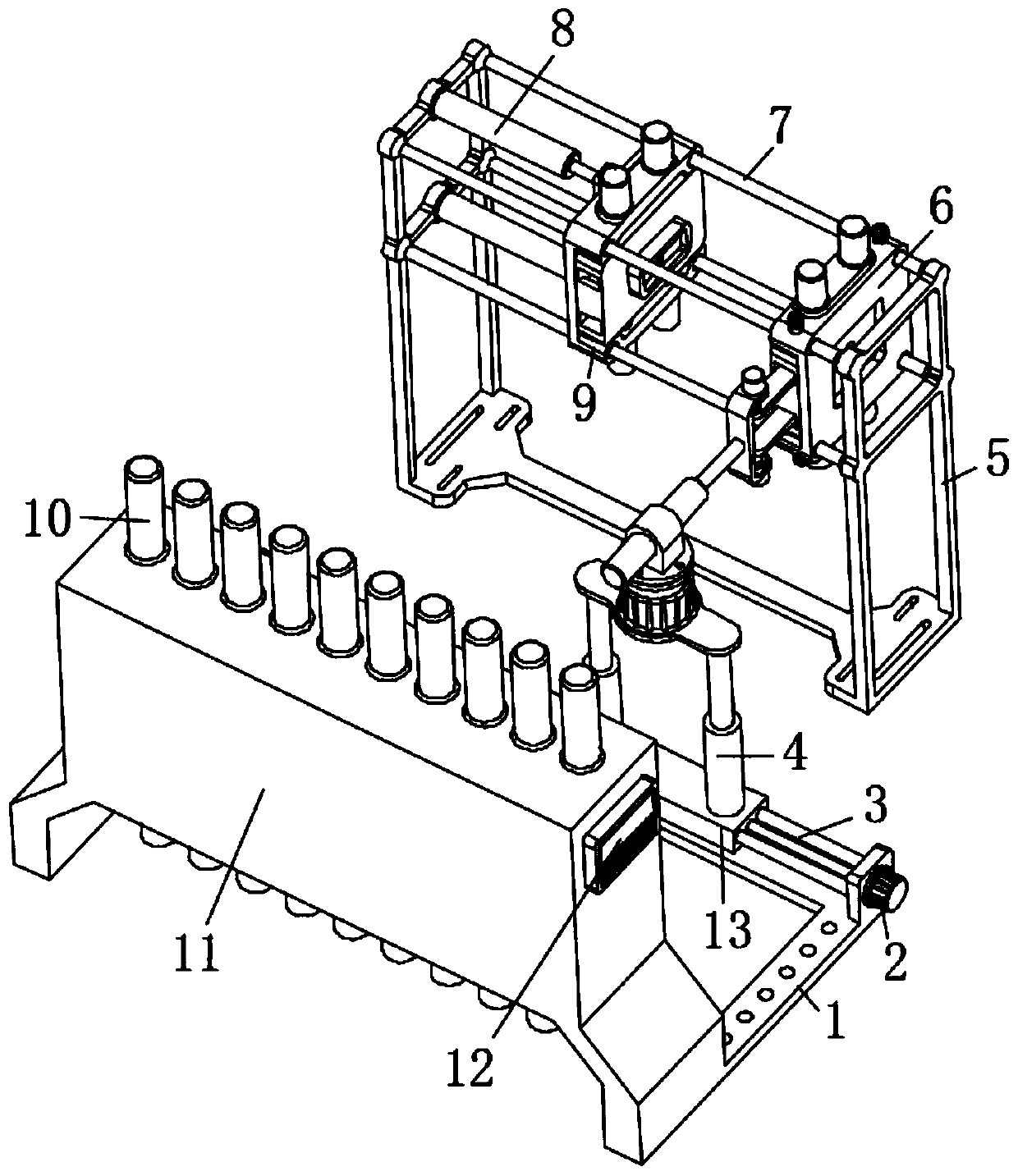
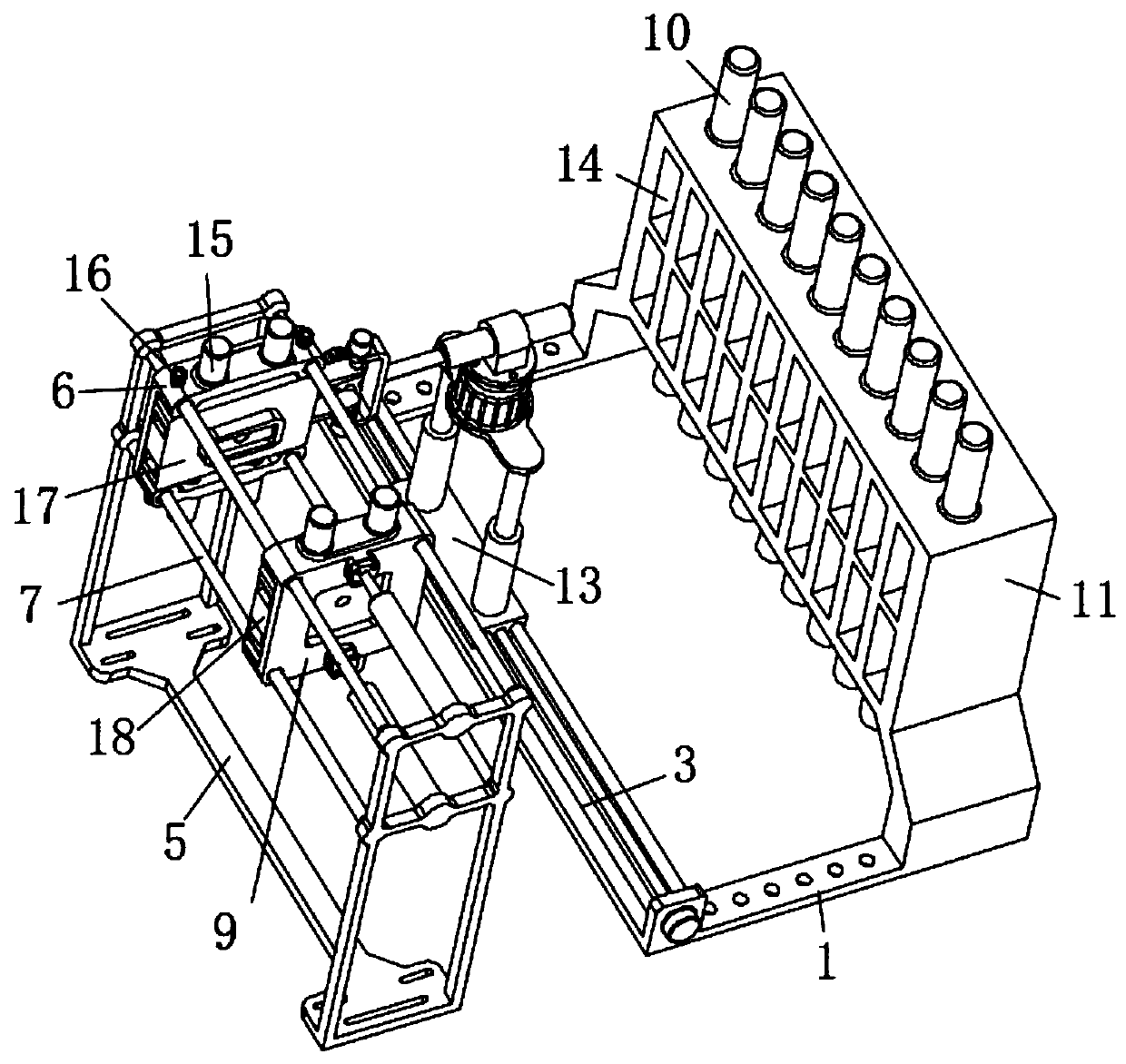
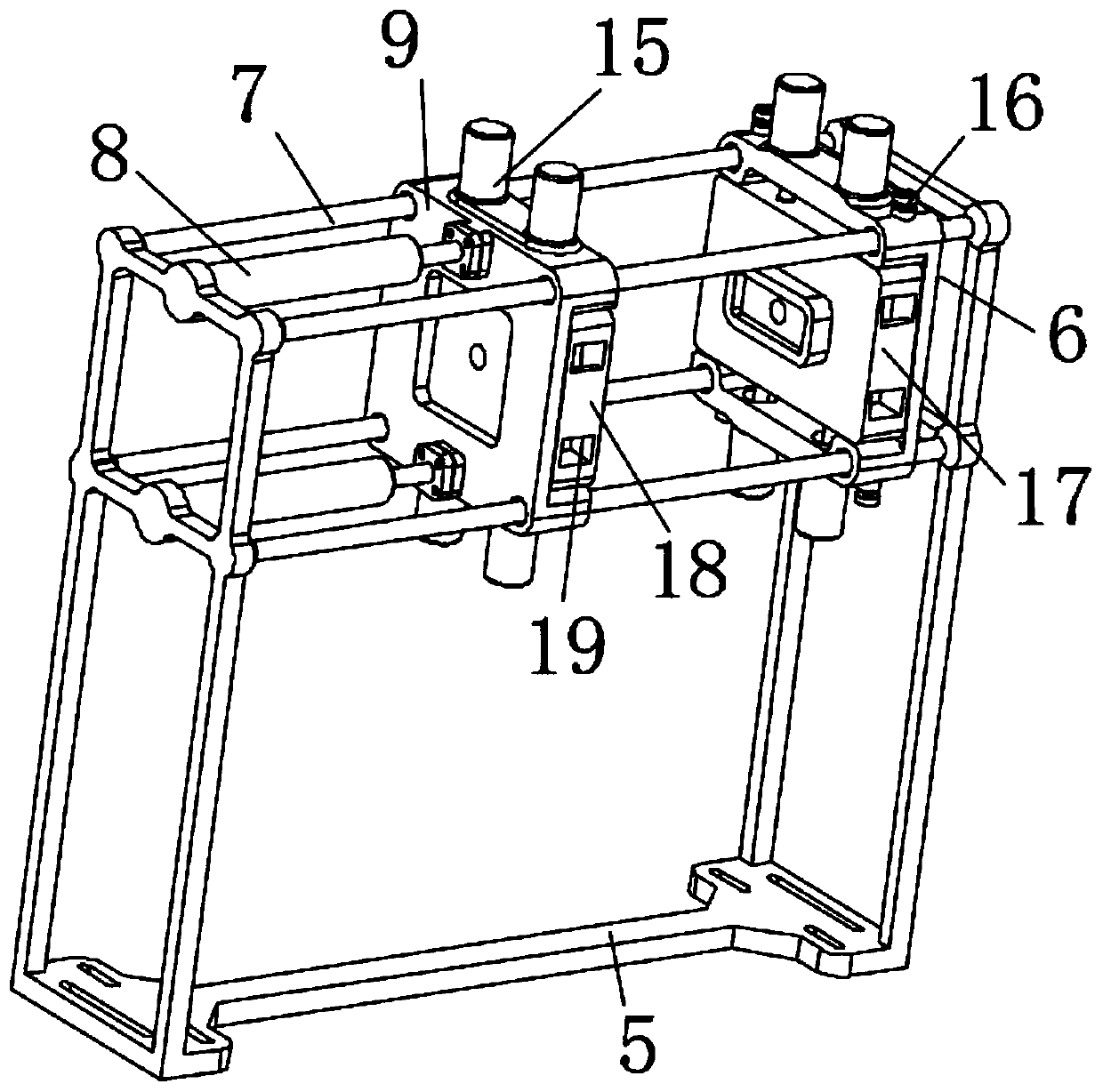
[0023] see Figure 1 to Figure 4 , the present invention provides a technical solution: a mold change structure for injection molding machine processing, including a base 1 and a fixed frame 5, a slide bar 7 is installed on the top of the fixed frame 5 through bolts, and a slide bar 7 is installed on the left side of the slide bar 7 Sliding mounting seat 9, the right side of slide bar 7 is fixedly installed with fixed mounting seat 6 by fixing screw bu...


PUM


Abstract

The invention relates to the technical field of injection moulding equipment, in particular to a mould change structure for an injection moulding machine. The mould change structure comprises a base and a fixed frame, wherein a slide rod is fixedly mounted above the fixed frame through a bolt; the left side of the slide rod is equipped with a slide mounting base in a sliding mode; and the right side of the slide rod is fixedly equipped with a fixed mounting base through a fixed screw knob. The mould change structure has the beneficial effects: a placing slot in a placing frame can be utilizedfor perform concentrated management on a mould, so that the problem that a conventional mould is placed disorderly and is difficult in maintenance is effectively avoided; moreover, a movable base further can be matched with a clamping arm for changing the mould on each injection moulding machine, so that conventional manual mould changing operation can be effectively replaced, better mould changeefficiency is provided, and consumption on labor power is reduced. The device can utilize a first positioning pushing rod and a second positioning pushing rod to realize quick clamping on the mould, so that complex operation of a mould changing process can be effectively reduced, and mould changing efficiency is improved.

Description

technical field [0001] The invention relates to the technical field of injection molding equipment, in particular to a mold changing structure for injection molding machine processing. Background technique [0002] An injection molding machine is a device that forms plastic products of various shapes by injecting thermoplastic or thermosetting plastic into a mold. In the process of using the injection molding machine, different molds can be replaced to realize the production of different products, but the existing mold replacement of the injection molding machine is mainly done manually, and the mold of the injection molding machine is very heavy, resulting in not only slow replacement speed, but also The physical exertion of workers is also serious, and the mold cannot be placed too far away from the injection molding machine, which makes it difficult to centrally manage the mold. [0003] If a new type of automatic mold changing equipment that can quickly change the mold ...

Claims


Application Information

Patent Timeline
IPC IPC(8): B29C45/17
CPCB29C45/1742B29C45/1756
Inventor 白文斌
Owner 上海金通塑料模具制品有限公司
Learn More