
Clamping mechanism of medical robot

A clamping mechanism and robot technology, applied in the field of robots, can solve the problems of surface damage of the clamping object, complex clamping mechanism structure, general clamping effect, etc., and achieve the effect of avoiding maintenance difficulties, simple structure, and avoiding water contact.

Inactive Publication Date: 2019-01-25
NANJING LI HANG IND INST OF BIONIC TECH LTD
View PDF13 Cites 1 Cited by
  • Summary
  • Abstract
  • Description
  • Claims
  • Application Information

AI Technical Summary

Problems solved by technology

[0002] The clamping mechanism of a medical robot is a clamping mechanism used on a medical robot. It is mainly used for the robot to clamp objects. It is a very important mechanism of a medical robot and has a good effect. However, the existing There are certain deficiencies in the clamping mechanism of the medical robot that need to be improved; the existing clamping mechanism of the medical robot has certain disadvantages in use. Firstly, the structure of the existing clamping mechanism is very complicated, difficult to maintain, and The clamping effect is average, and secondly, there is no protection function, which is easy to cause damage to the surface of the clamped object, and the safety is not high, which brings certain adverse effects to the actual use. Therefore, we propose a clamping mechanism for medical robots

Method used


Image

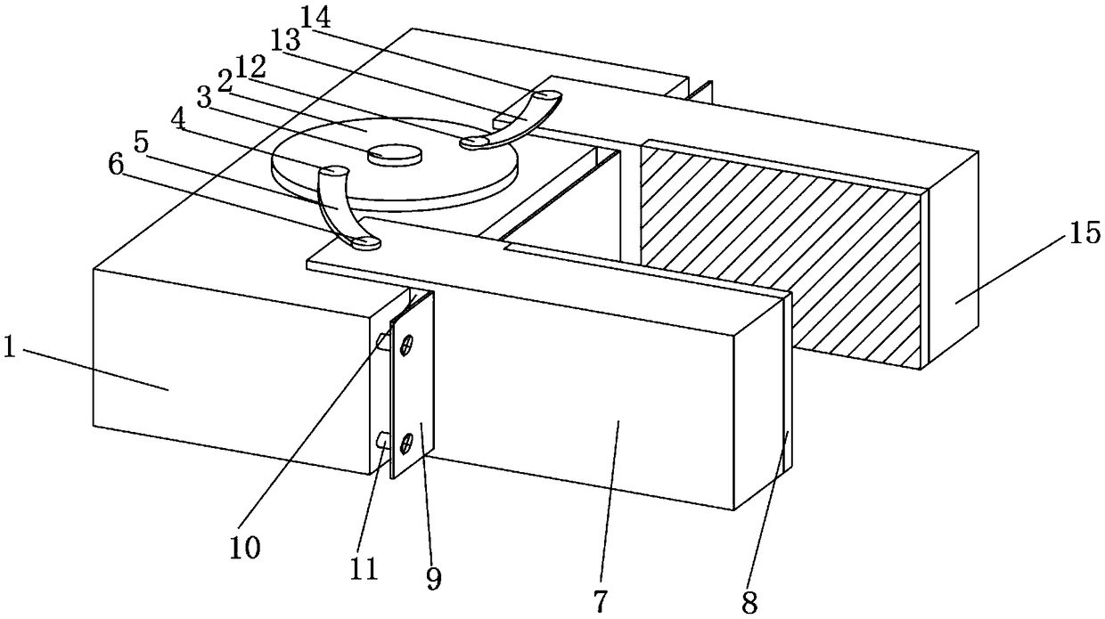
  • Clamping mechanism of medical robot
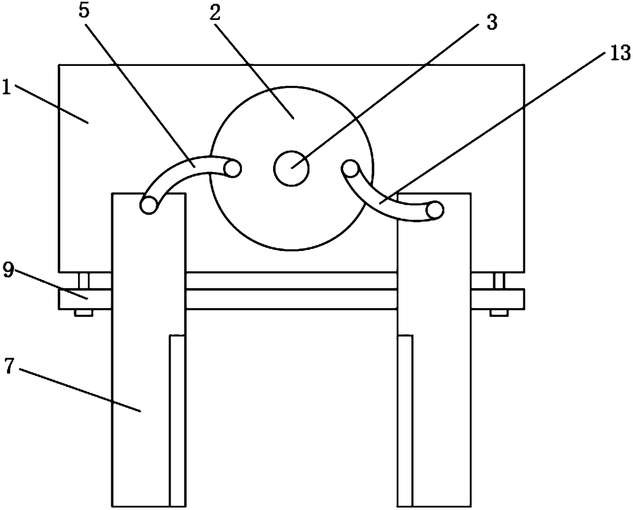
  • Clamping mechanism of medical robot
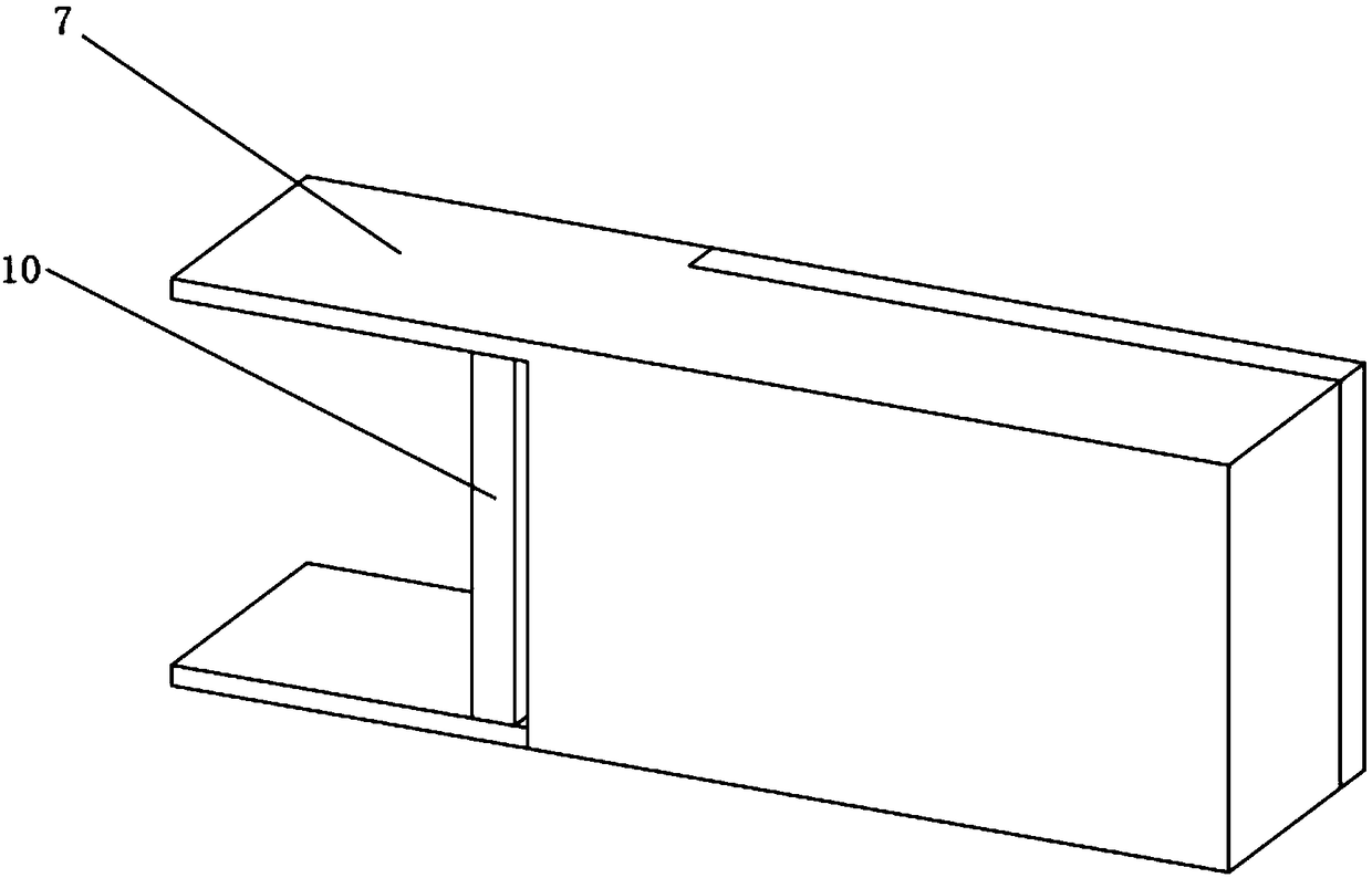
  • Clamping mechanism of medical robot

Examples


Embodiment 1

[0031] Super-hydrophobic wear-resistant coating, including the following raw materials in parts by weight: 90 parts of copper sulfate, 60 parts of methacryloxyethyl phosphate, 20 parts of vinyl terephthalic acid, 225 parts of ethanol, diethylene triethylene 50 parts of amine pentaacetic dianhydride, 60 parts of ethyl orthosilicate, 150 parts of zinc oxide, 90 parts of manganese dioxide, 15 parts of licorice essence, 65 parts of tetraethylenepentamine, and 600 parts of water.

[0032] The preparation method of superhydrophobic wear-resistant coating, comprises the following steps:

[0033] Step 1, mixing copper sulfate, methacryloyloxyethyl phosphate, and vinyl terephthalic acid, adding to ethanol and stirring evenly to obtain mixture 1;

[0034] Step 2: Mix water, diethylenetriaminepentaacetic dianhydride, and ethyl orthosilicate, heat to 200-300°C, keep for 5 hours, add zinc oxide, manganese dioxide, and licorice essence, stir evenly with magnetic force, and rotate Be 1330r / ...

Embodiment 2

[0038] Super-hydrophobic wear-resistant coating, including the following raw materials in parts by weight: 80 parts of copper sulfate, 40 parts of methacryloxyethyl phosphate, 10 parts of vinyl terephthalic acid, 220 parts of ethanol, diethylene triethylene 40 parts of amine pentaacetic dianhydride, 30 parts of ethyl orthosilicate, 100 parts of zinc oxide, 40 parts of manganese dioxide, 20 parts of licorice essence, 70 parts of tetraethylenepentamine, and 800 parts of water.

[0039] The preparation method of superhydrophobic wear-resistant coating, comprises the following steps:

[0040] Step 1, mixing copper sulfate, methacryloxyethyl phosphate, and vinyl terephthalic acid, adding to ethanol and stirring evenly to obtain mixture 1;

[0041] Step 2: Mix water, diethylenetriaminepentaacetic dianhydride, and ethyl orthosilicate, heat to 200-300°C, keep for 6 hours, add zinc oxide, manganese dioxide, and licorice essence, stir evenly with magnetic force, Be 1300r / min, obtain mixt...

Embodiment 3

[0045] Super-hydrophobic wear-resistant coating, including the following raw materials in parts by weight: 100 parts of copper sulfate, 90 parts of methacryloxyethyl phosphate, 30 parts of vinyl terephthalic acid, 230 parts of ethanol, diethylene triethylene 60 parts of amine pentaacetic dianhydride, 90 parts of ethyl orthosilicate, 200 parts of zinc oxide, 120 parts of manganese dioxide, 10 parts of licorice essence, 60 parts of tetraethylenepentamine, 400 parts of water.

[0046] The preparation method of superhydrophobic wear-resistant coating, comprises the following steps:

[0047] Step 1, mixing copper sulfate, methacryloxyethyl phosphate, and vinyl terephthalic acid, adding to ethanol and stirring evenly to obtain mixture 1;

[0048] Step 2: Mix water, diethylenetriaminepentaacetic dianhydride, and ethyl orthosilicate, heat to 200-300°C, keep for 4 hours, add zinc oxide, manganese dioxide, and licorice essence, stir evenly with magnetic force, and rotate Be 1400r / min, ...


PUM


Abstract

The invention discloses a clamping mechanism of a medical robot. The clamping mechanism comprises a clamping seat and is characterized in that a central shaft is movably mounted at the upper end of the clamping seat, the outer surface of the central shaft is provided with a rotary disc, a position, close to one side, of the top of the rotary disc is provided with a first connecting shaft, a firstarc-shaped rod is connected between the first connecting shaft and the rotary disc, the other end of the first arc-shaped rod is provided with a second connecting shaft, and the second connecting shaft penetrates the first arc-shaped rod to be movably connected with a first clamping block. The clamping mechanism has the advantages that the clamping mechanism is provided with the rotary disc, the first arc-shaped rod and a second arc-shaped rod which are coordinated, and the rotation of the rotary disc drives the first arc-shaped rod and the second arc-shaped rod to move in an arc-shaped mannerso as to drive the first clamping block and a second clamping block to move; the clamping mechanism is simple in structure, convenient to maintain and promising in application prospect, and skid resistance and object surface scratch preventing are achieved by rubber pads.

Description

technical field [0001] The invention relates to the field of robots, in particular to a clamping mechanism of a medical robot. Background technique [0002] The clamping mechanism of a medical robot is a clamping mechanism used on a medical robot. It is mainly used for the robot to clamp objects. It is a very important mechanism of a medical robot and has a good effect. However, the existing There are certain deficiencies in the clamping mechanism of medical robots that need to be improved; the existing clamping mechanisms of medical robots have certain disadvantages in use. Firstly, the existing clamping mechanisms are very complicated in structure, difficult to maintain, and The clamping effect is average, and secondly, there is no protection function, which is easy to cause damage to the surface of the clamped object, and the safety is not high, which brings certain adverse effects to the actual use. Therefore, we propose a clamping mechanism for medical robots. Content...

Claims


Application Information

Patent Timeline
Patent Type & Authority Applications(China)
IPC IPC(8): B25J15/08C09D4/02C09D7/61C09D7/63
CPCC09D7/63C09D4/00C09D7/61B25J15/08
Inventor 陆格珠
Owner NANJING LI HANG IND INST OF BIONIC TECH LTD
Learn More