
Receiver module and lidar including it

A laser radar and module technology, applied in the re-radiation of electromagnetic waves, instruments, utilization of re-radiation, etc., can solve the problems of increasing wiring area, radar crosstalk, high gain inconsistency, etc., to simplify the installation and adjustment process and reduce the temperature gradient , good long-distance consistency effect

Active Publication Date: 2020-11-27
HESAI TECH CO LTD
View PDF12 Cites 26 Cited by
  • Summary
  • Abstract
  • Description
  • Claims
  • Application Information

AI Technical Summary

Problems solved by technology

The lidar system has an important application in the unmanned driving system. In this application, the lidar needs to have high imaging frame rate, high resolution, long-range ranging capability, small size, high reliability, and low cost. The traditional lidar system is very Difficult to meet these performance
[0003] In the current laser radar, discrete devices are usually used to construct the detection and receiving system. For example, a 64-line laser radar has 64 APDs, which requires 64 TIA transimpedance circuits. Using discrete devices requires a large PCB board area for wiring. Considering Considering the volume requirements of the radar itself, it is unreasonable to use a large PCB. Currently, multiple boards are connected through connectors to increase the wiring area, which brings a series of technical defects.
[0004] Taking the 64-line lidar as an example, the pin spacing of the connector is small, and the wiring from the 64-way APD to the transimpedance amplifier needs to be converged on the connector first, and then diverge to the receiving board 1 and receiving board 2 after passing through the connector. On the one hand, the electrical isolation of the pin itself is relatively low. On the other hand, the wiring distance corresponding to the pin cannot be enlarged, and the length of the parallel wiring is very long, resulting in a low isolation of the wiring, which will lead to different channels of the radar. crosstalk between
[0005] In addition, the wiring of the 64-channel APD readout circuit is not the same, resulting in different parasitic parameters on the PCB board for different channels, which affects the response characteristics of each channel, resulting in high inconsistency in distance measurement for 64 channels
[0006] At the same time, the gain of the avalanche photodiode APD is very sensitive to temperature. The 64 APDs on the receiving board are located at scattered positions on the board. When the radar is working, the temperatures at these positions are not equal, and there is a certain gradient. Good heat dissipation or uniform The thermal structure can effectively reduce such a gradient, but the receiving module composed of 4 PCB boards takes up a lot of space, it is difficult to install a heat dissipation or heat uniform structure, and there is inevitably a high gain inconsistency

Method used


Image

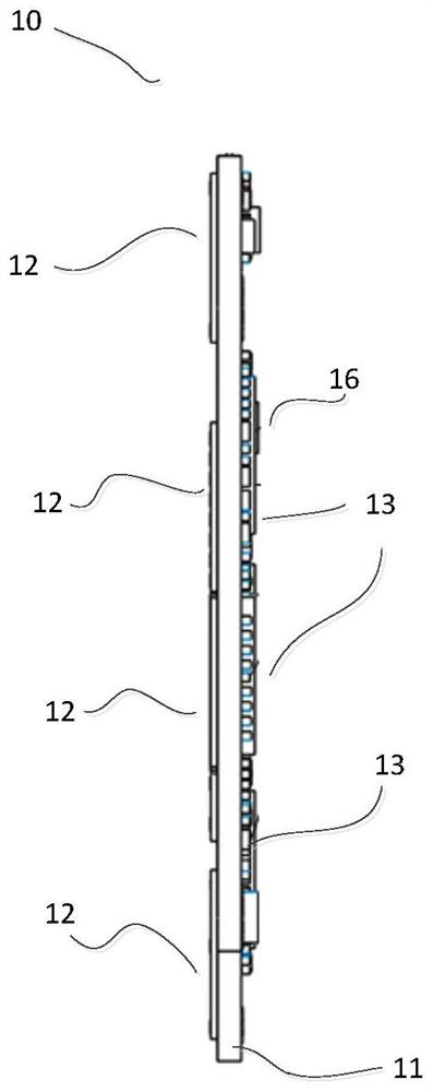
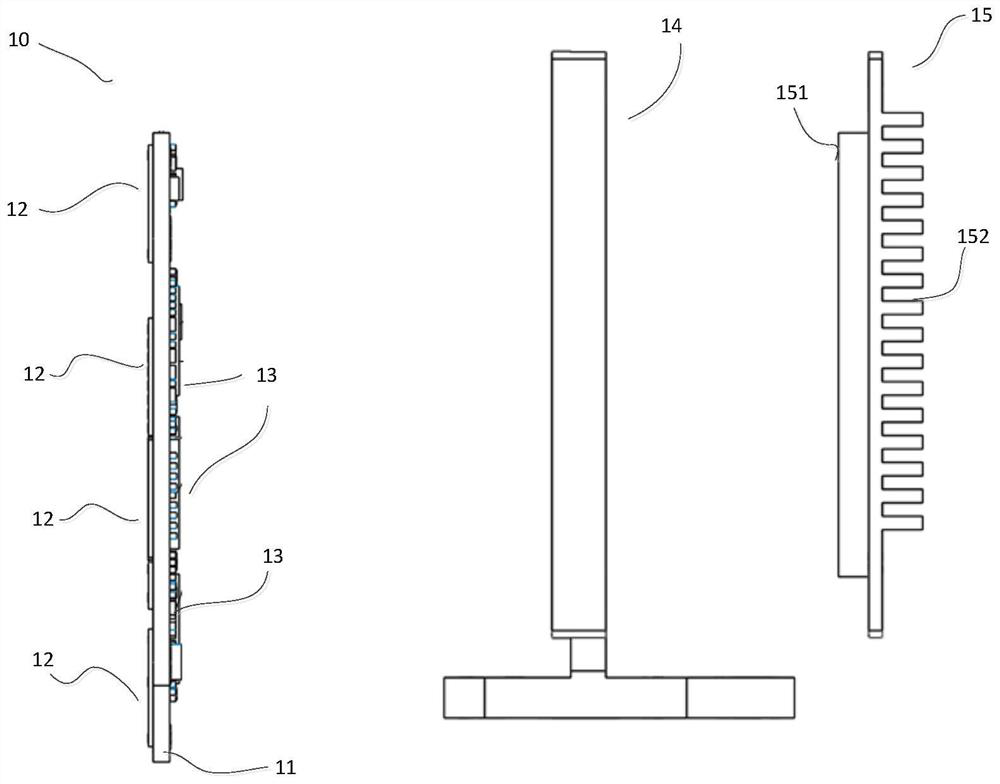
  • Receiver module and lidar including it
  • Receiver module and lidar including it
  • Receiver module and lidar including it

Examples


Embodiment Construction

[0033] In the following, only some exemplary embodiments are briefly described. As those skilled in the art would realize, the described embodiments may be modified in various different ways, all without departing from the spirit or scope of the present invention. Accordingly, the drawings and descriptions are to be regarded as illustrative in nature and not restrictive.

[0034] In describing the present invention, it is to be understood that the terms "center", "longitudinal", "transverse", "length", "width", "thickness", "upper", "lower", "front", " Back", "Left", "Right", "Straight", "Horizontal", "Top", "Bottom", "Inner", "Outer", "Clockwise", "Counterclockwise", etc. or The positional relationship is based on the orientation or positional relationship shown in the drawings, which is only for the convenience of describing the present invention and simplifying the description, rather than indicating or implying that the referred device or element must have a specific orie...


PUM


Abstract

The invention relates to a receiving module that can be used for laser radar, comprising: a PCB substrate, the PCB substrate has a first side and a second side; a photoelectric sensor array, including a plurality of photoelectric sensors, and the photoelectric sensor array is arranged on the the first side of the PCB substrate; and a readout chip, the readout chip is arranged on the second side of the PCB substrate, and is coupled to the photoelectric sensor array, configured to receive and read the photoelectric sensor output of the photosensors in the array.

Description

technical field [0001] The invention relates to the field of optoelectronic technology, in particular to a receiving module and a laser radar including the same. Background technique [0002] The laser radar system is currently widely used in the field of unmanned driving, including the laser emitting system and the detection receiving system. The emitted laser light is reflected and received by the detection system after encountering the target. The distance of the corresponding target point can be measured by measuring the round-trip time of the laser. (such as the time-of-flight method), when the entire target area is scanned and detected, three-dimensional imaging can finally be achieved. The lidar system has an important application in the unmanned driving system. In this application, the lidar needs to have high imaging frame rate, high resolution, long-range ranging capability, small size, high reliability, and low cost. The traditional lidar system is very It is dif...

Claims


Application Information

Patent Timeline
Patent Type & Authority Patents(China)
IPC IPC(8): G01S7/481
CPCG01S7/4863H01L25/042G01S7/4816G01S17/89G01S7/4914H05K1/181H05K2201/10151H05K2201/10545H05K1/0243H01L31/107
Inventor 闫凯民向少卿
Owner HESAI TECH CO LTD
Learn More