
Charging, communication circuits and methods and charging devices, accessories and systems therefor

A communication circuit and charging power supply technology, applied in the electronic field, can solve the problems of difficult product miniaturization and high hardware cost, and achieve the effects of reducing potential interference, improving recognition, and reducing the probability of misjudgment

Active Publication Date: 2021-09-07
ZHUHAI JIELI TECH
View PDF0 Cites 0 Cited by
  • Summary
  • Abstract
  • Description
  • Claims
  • Application Information

AI Technical Summary

Problems solved by technology

The cost of hardware is high and the product is difficult to miniaturize

Method used


Image

  • Charging, communication circuits and methods and charging devices, accessories and systems therefor
  • Charging, communication circuits and methods and charging devices, accessories and systems therefor
  • Charging, communication circuits and methods and charging devices, accessories and systems therefor

Examples


Embodiment 1

[0053] In order to initiate a request for establishing a communication connection more specifically and effectively, this embodiment discloses a communication circuit, which is suitable for a charging power supply end.

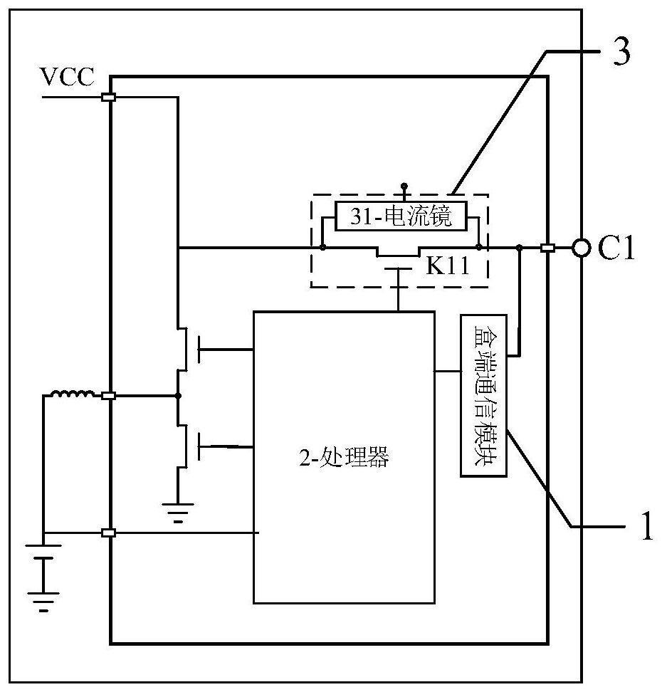
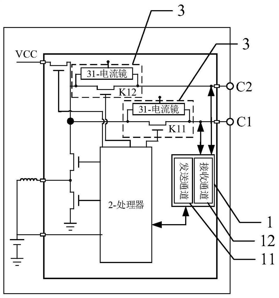
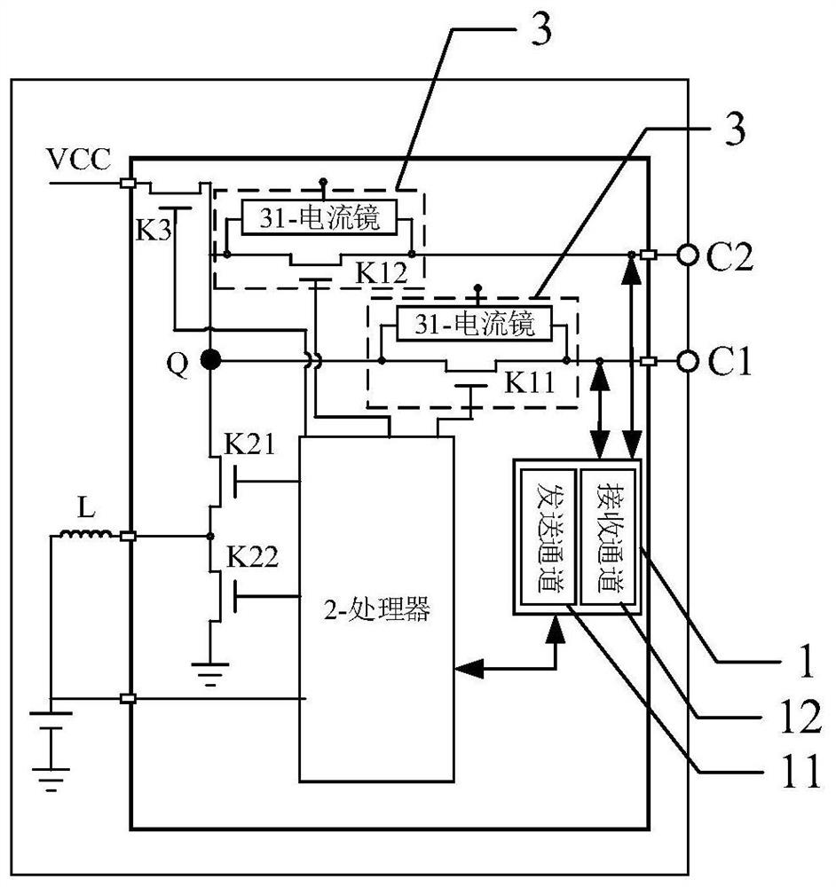
[0054] Please refer to figure 1 , is a schematic structural diagram of a communication circuit disclosed in this embodiment, the communication circuit is suitable for charging equipment, such as charging boxes, mobile power supplies, etc., the communication circuit includes: a box-side communication module 1, a processor 2 and a path establishment module 3 ,in:

[0055] The path establishment module 3 includes a potential switch unit K11 and a current mirror 31. The potential switch unit K11 is connected between the charging power supply VCC and the potential output terminal C1. When the potential switch unit K11 is turned on, the charging power supply VCC can provide its power to the potential output Terminal C1, in order to provide power to the device to be...

Embodiment 2

[0086] In order to initiate a request for establishing a communication connection more specifically and effectively, this embodiment discloses a communication circuit, which is suitable for the device to be charged. In a specific embodiment, the device to be charged is the charging The equipment used in conjunction with the equipment can be, for example, smart wearable devices such as earphones and bracelets, audio-visual equipment such as MP3 and MP4, or smart accessories with data processing capabilities that match smart terminals.

[0087] Please refer to Figure 5 , is a schematic structural diagram of a charging communication circuit disclosed in this embodiment, the charging communication circuit includes: a machine-side switch unit K4 and a machine-side communication module 4, wherein,

[0088] The terminal switch unit K4 is connected between the potential receiving terminal C3 and the built-in battery of the terminal. The potential receiving terminal C3 is used to prov...


PUM


Abstract

The present invention provides a charging and communication circuit and method and its charging equipment, accessories and system, including: a box-side communication module, used to generate a box-side communication request signal and transmit it to the potential output terminal, and the potential of the box-side communication request signal is not It is equal to the high potential and low potential when the potential output terminal provides charging power; the path establishment module is used to disconnect the charging power output to the potential output terminal according to the communication request signal of the box terminal, so as to request the terminal connected to the potential output terminal to establish a communication connection . Therefore, the potential interference caused by the charging power source is reduced, so that when the terminal connected to the potential output terminal is requested to establish a communication connection, the identification of the communication connection request is improved, and the communication connection establishment request is more targeted and effectively initiated. .

Description

technical field [0001] The present invention relates to the field of electronic technology, in particular to a charging and communication circuit and method, as well as charging equipment, accessories and systems thereof. Background technique [0002] With the development of technology, wireless headsets (such as Bluetooth headsets) are becoming more and more popular. At present, a charging box is usually configured for a wireless earphone, and most of the charging box and the wireless earphone are charged through two corresponding power contact points. There are many communication requirements between the charging box and the wireless headset, including: after the wireless headset is inserted into the charging box, the battery level of the headset is detected; the wireless headset queries the battery level of the charging box; the button pairing function on the wireless headset charging box, etc. [0003] When the existing charging box communicates with the wireless earpho...

Claims


Application Information

Patent Timeline
Patent Type & Authority Patents(China)
IPC IPC(8): H02J7/00
CPCH02J7/00
Inventor 黄海涛张启明魏荣城翁建城
Owner ZHUHAI JIELI TECH
Learn More