
Immersed liquid cooling battery pack

A liquid-cooled battery, immersion technology, applied in batteries, secondary batteries, circuits, etc., can solve the problems of poor cooling effect, slow cooling by air cooling, uneven direct cooling, etc., and achieve automatic adjustment of heat dissipation power and uniform cooling. Liquid temperature, the effect of improving temperature consistency

Pending Publication Date: 2020-01-24
FUJIAN YIDONGLI ELECTRONICS TECH CO LTD
View PDF0 Cites 9 Cited by
  • Summary
  • Abstract
  • Description
  • Claims
  • Application Information

AI Technical Summary

Problems solved by technology

[0003] Generally speaking, the higher the power, the greater the charge and discharge rate required by the battery, and the greater the heat generated; in some high-power applications, such as energy storage and frequency modulation, in order to adapt to high-power applications, it is necessary to increase the battery capacity to reduce the charge and discharge rate. This will increase the cost of the battery; in addition, when the battery is thermally out of control, a large amount of heat is generated instantaneously. At this time, if the heat dissipation system does not have time to cool the battery, it will cause the danger of fire and explosion; how to improve the heat dissipation effect of the battery is the key to solving these problems
[0004] Now for the battery loaded, the heat dissipation methods are mainly divided into direct cooling, air cooling and liquid cooling. The direct cooling is uneven and the cooling effect is not good; The cooling liquid circulates to dissipate heat. Liquid cooling pipes need to be arranged, which takes up a lot of space. The system is complex and expensive, and there are hidden dangers of liquid leakage. Therefore, these three methods cannot meet the requirements of battery heat dissipation in high-power applications.

Method used


Image

  • Immersed liquid cooling battery pack
  • Immersed liquid cooling battery pack
  • Immersed liquid cooling battery pack

Examples


Embodiment Construction

[0017] In order to make the object and technical solutions of the present invention clearer, the present invention will be further described below in conjunction with the accompanying drawings and embodiments:

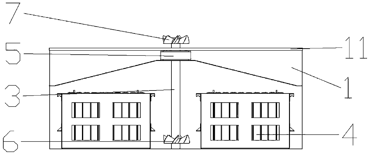
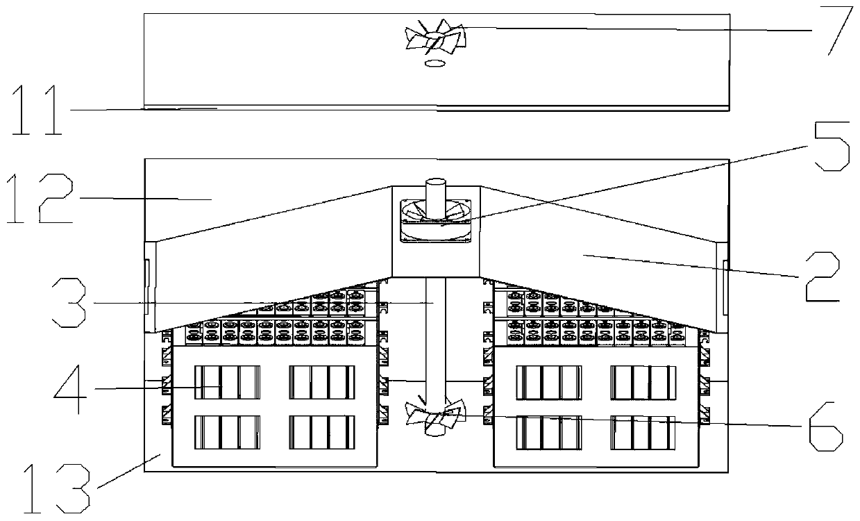
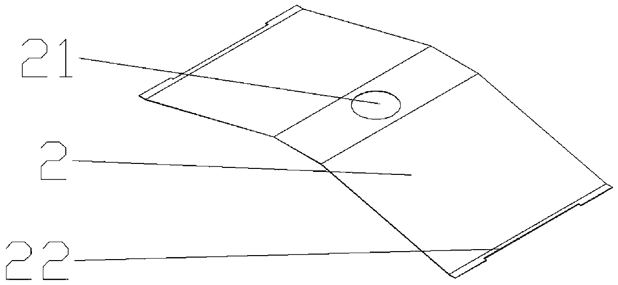
[0018] Such as Figure 1 ~ Figure 3 A submerged liquid-cooled battery pack shown includes: a case cover 11; a battery case 1 forming a sealed space with the case cover 11; a steam guide plate 2, which is a wedge-shaped plate protruding upward in the middle; installed on the battery In the middle part of the box 1, the battery box is divided into an upper box 12 and a lower box 13; a steam hole 21 is located in the middle of the steam guide plate 2, and communicates with the upper box 12 and the lower box 13; the leakage tank 22 has a total Two, respectively arranged on both sides of the steam guide plate 2, communicating with the upper box 12 and the lower box 13; the battery 4 is installed and fixed in the lower box 13; the cooling liquid is injected into the lower bo...


PUM


Abstract

The invention provides an immersed liquid cooling battery pack. The battery pack includes a case cover, a battery box forming the sealed space with the box cover, a steam guide plate which is a wedge-shaped plate with the middle protruding upwards, a partition plate which is mounted in the middle of the battery box and divides the battery box into an upper box and a lower box, a steam hole which is positioned at the middle of the steam guide plate and is communicated with an upper box and a lower box, two liquid leakage grooves which are formed on two sides of the steam guide plate correspondingly and communicate with the upper box and the lower box, a battery mounted and fixed in the lower box, the cooling liquid which is injected into the lower box to soak the battery, a power fan mounted and fixed on the steam hole on the steam guide plate, a stirring fan which is fixedly arranged at the bottom of the lower box and is soaked by the cooling liquid, a cooling fan mounted and fixed onthe box cover, and a rotating shaft is a rotating shaft which is fixedly mounted by the power fan, the stirring fan and the cooling fan together, wherein the the cooling liquid is low-boiling-point insulating liquid with the boiling point of 30-70 DEG C.

Description

technical field [0001] The invention relates to a submerged liquid-cooled battery pack. Background technique [0002] The current shortage and consumption of oil have caused a huge burden on the country, and the development of environmental protection awareness and the human environment have also put forward requirements for transportation tools. Therefore, the development prospects of new energy vehicles are broad. At present, a major problem facing new energy vehicles is to solve Endurance issues and safety issues, and the heat dissipation of the battery is a key part of it. [0003] Generally speaking, the higher the power, the greater the charge and discharge rate required by the battery, and the greater the heat generated; in some high-power applications, such as energy storage and frequency modulation, in order to adapt to high-power applications, it is necessary to increase the battery capacity to reduce the charge and discharge rate. This will increase the cost of t...

Claims


Application Information

Patent Timeline
IPC IPC(8): H01M10/613H01M10/617H01M10/625H01M10/6556H01M10/6563H01M10/6567
CPCH01M10/613H01M10/617H01M10/625H01M10/6556H01M10/6563H01M10/6567H01M2220/20Y02E60/10
Inventor 张建明曾庆磊黄剑邓长水王福锦
Owner FUJIAN YIDONGLI ELECTRONICS TECH CO LTD
Learn More