Method for controlling welding deformation of high-energy beam

A high-energy beam welding and laser welding technology, which is applied in the direction of electron beam welding equipment, welding equipment, laser welding equipment, etc., can solve the problems of affecting the processing accuracy of the workpiece, the fatigue of the workpiece and other performance effects, and achieves simple operation and restraint deformation effect

Pending Publication Date: 2020-01-24
HEFEI INSTITUTES OF PHYSICAL SCIENCE - CHINESE ACAD OF SCI
View PDF10 Cites 1 Cited by
  • Summary
  • Abstract
  • Description
  • Claims
  • Application Information

AI Technical Summary

Problems solved by technology

Some workpieces cannot remove welding residual stress by annealing in the furnace due to their own particularity, so the residual stress in the workpiece will not only affect the machining accuracy of the workpiece, but also have a great impact on the fatigue and other performance of the workpiece

Method used


Image

  • Method for controlling welding deformation of high-energy beam

Examples


Embodiment 1

[0026] A method for controlling deformation of high-energy beam welding in Embodiment 1 is carried out in the following steps:

[0027] Step 1. Groove processing: process a groove with a blunt edge between the two workpieces to be welded.

[0028] Step 2. Assembly: Clean the welding surfaces of the two workpieces to be welded with alcohol or acetone and place them on the welding platform, assemble the bevel side on the bottom and the blunt side on the top, and fix the workpieces through the pressure plate.

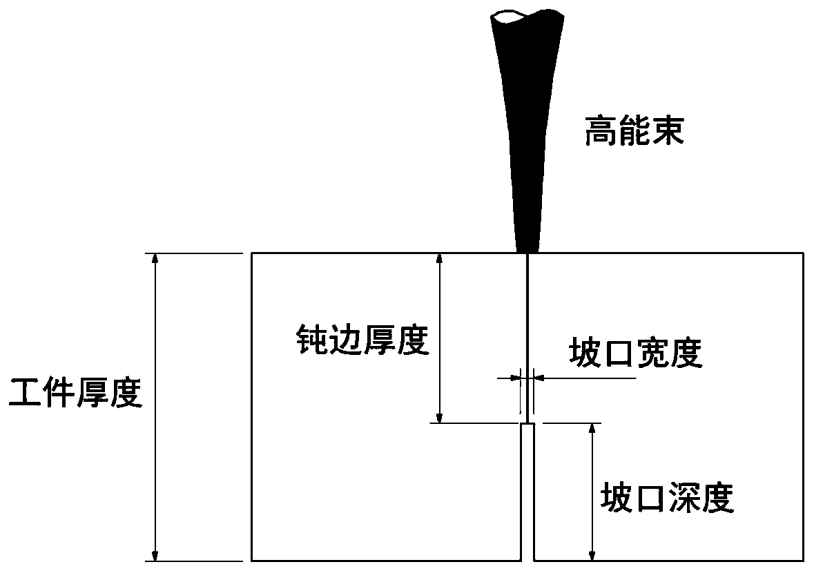
[0029] Step 3, welding: welding the workpiece by high energy beam welding. see figure 1 .

[0030] Specifically, the welding method in this embodiment is laser non-scanning self-fusion welding;

[0031] Specifically, the laser used in this embodiment is a fiber laser, and the beam mode is multimode;

[0032] Specifically, the groove depth in this embodiment is 5mm, and the groove width is 0.3mm;

[0033] Specifically, the blunt edge thickness in this embodiment is 5mm...

Embodiment 2

[0037] A method for controlling the deformation of high-energy beam welding in Embodiment 2 is carried out in the following steps:

[0038] Step 1. Groove processing: process a groove with a blunt edge between the two workpieces to be welded.

[0039] Step 2. Assembly: Clean the welding surfaces of the two workpieces to be welded with alcohol or acetone and place them on the welding platform, assemble the bevel side on the bottom and the blunt side on the top, and fix the workpieces through the pressure plate.

[0040] Step 3, welding: welding the workpiece by high energy beam welding.

[0041] Specifically, the welding method in this embodiment is laser non-scanning self-fusion welding;

[0042] Specifically, the laser used in this embodiment is a fiber laser, and the beam mode is multimode;

[0043] Specifically, the groove depth in this embodiment is 6mm, and the groove width is 0.3mm;

[0044] Specifically, the blunt edge thickness in this embodiment is 14mm;

[0045] ...


PUM

PropertyMeasurementUnit
widthaaaaaaaaaa

Abstract

The invention discloses a method for controlling welding deformation of a high-energy beam. The method is mainly applied to the fields of laser welding and electronic beam welding. According to the basic principle of the method, a welding groove is designed to affect the flow behavior and distribution status of metal melt, and special stress distribution is formed in the solidification process toreduce welding deformation. A weld joint is characterized in that a truncated edge is located on the upper portion of the joint, a groove gap in a certain shape is reserved in the lower portion of thejoint, the groove in the form can achieve a through small deep melting hole of high-energy beam welding more easily, the melt can flow more smoothly, the gap in the lower portion can bring more meltand heat to the lower portion, and the melt and energy can be vertically distributed more uniformly. Because few materials are removed for forming the groove, the section of the whole weld joint is hardly affected, and welding materials do not need to be particularly added. By the adoption of the method, welding deformation can be effectively reduced, the stability in the welding process is improved, and the method is easy to implement and has promotional value.

Description

technical field [0001] The invention belongs to the technical field of high-energy beam welding, and in particular relates to a method for controlling deformation of high-energy beam welding. Background technique [0002] Welding deformation is one of the most common welding defects in the welding process. Once it occurs, it is difficult and cumbersome to deal with, which limits the popularization and application of welding technology to a certain extent. High-energy beam welding is the same as other fusion welding methods. Although its deformation is much smaller than that of ordinary arc welding, welding deformation is inevitable. Therefore, welding deformation is also one of the problems that high-energy beam welding needs to face directly. [0003] Usually, the cross-sectional shape of the weld seam is inconsistent with top width and bottom narrowness. It is precisely because of the uniformity of the weld seam that the shrinkage at different positions of the weld seam is...

Claims


Application Information

Patent Timeline
Patent Type & Authority Applications(China)
IPC IPC(8): B23K26/21B23K26/348B23K26/60B23K15/00
CPCB23K15/00B23K26/21B23K26/348B23K26/60
Inventor 方超卫靖信纪军刘劲戴文华
Owner HEFEI INSTITUTES OF PHYSICAL SCIENCE - CHINESE ACAD OF SCI
Why Eureka
Try Eureka