
Online Monitoring Method of Lubricating Oil Wear Debris Based on Optical Low Coherence Imaging

A low-coherence, detection method technology, used in measurement devices, scientific instruments, suspension and porous material analysis, etc., can solve the problem of inability to accurately judge the wear stage, incomplete size range of wear debris, and inability to extract and identify wear debris image features. and other problems, to achieve the effect of fast speed, accurate and fast recognition, and improved accuracy and speed

Active Publication Date: 2020-09-01
NANJING UNIV OF AERONAUTICS & ASTRONAUTICS
View PDF13 Cites 0 Cited by
  • Summary
  • Abstract
  • Description
  • Claims
  • Application Information

AI Technical Summary

Problems solved by technology

[0003] At present, most wear debris online monitoring technologies can only monitor the quantity and type (ferromagnetic and non-ferromagnetic) of wear debris, and cannot perform feature extraction and identification of wear debris images; in addition, various existing sensors can The size range of the monitored wear debris is incomplete, and the wear stage cannot be accurately judged. In the future, the size range of the wear debris monitoring should strive to reach 1 ~ 1000um

Method used


Image

  • Online Monitoring Method of Lubricating Oil Wear Debris Based on Optical Low Coherence Imaging
  • Online Monitoring Method of Lubricating Oil Wear Debris Based on Optical Low Coherence Imaging
  • Online Monitoring Method of Lubricating Oil Wear Debris Based on Optical Low Coherence Imaging

Examples


Embodiment Construction

[0029] Aiming at the shortcomings of the existing technology, the solution of the present invention is to apply the optical low-coherence imaging technology to the on-line detection of wear debris, so that the quantity and shape characteristics of wear debris can be accurately and quickly identified, and the detection range of wear debris size is wide. Suitable for working in high electromagnetic interference environment.

[0030] Optical low coherence technology has been widely used since it was proposed. Different from the general optical interference technology, the optical low-coherence technology uses a broadband light source, so its coherence length is very short. By detecting the interference envelope, the information of the reflective surface of the sample can be obtained, and then the sample surface can be analyzed by the spatial domain processing technology. for imaging. Optical low-coherence imaging technology has high acquisition speed, simple structure, and more ...


PUM


Abstract

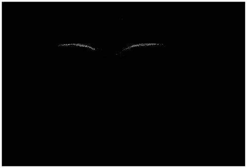
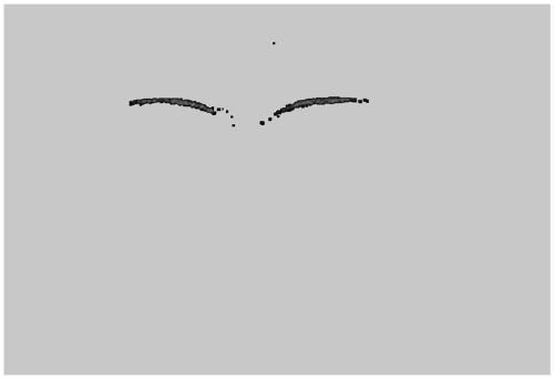
The invention discloses an online detection method of lubricating oil wear debris based on optical low-coherence imaging. The method includes the step of imaging wear debris, and the step of imaging wear debris is specifically as follows: continuous optical low-coherence imaging of the lubricant oil through a transparent window provided in the lubricant oil circulation loop, and scanning the lens during the imaging process The beam scanning surface is perpendicular to the oil flow direction to obtain a series of two-dimensional low-coherence images; the two-dimensional low-coherence images are converted into binary low-coherence images; the wear and tear in each binary low-coherence image is detected. Chip contours; perform three-dimensional reconstruction of all detected wear chip profiles along the oil flow direction to obtain the three-dimensional surface morphology of the wear chips. Compared with the existing technology, the present invention has better real-time performance, higher resolution, simpler structure, and more convenient construction and debugging.

Description

technical field [0001] The invention discloses an online detection method of lubricating oil wear debris, which can detect the information of lubricating oil wear debris in real time, thereby judging the health status of equipment, and belongs to the technical field of mechanical equipment health monitoring. Background technique [0002] At present, there are two main methods for detecting metal abrasive particles in lubricating oil of mechanical equipment: off-line and on-line detection. The off-line detection method has the advantages of high detection accuracy, can accurately determine the type and element composition of metal particles, and the particle shape characteristics, etc., but it takes a lot of time to collect oil samples and data, and it usually takes more than an hour to analyze an oil sample, or even as long as several months. A large amount of data shows that the offline detection method consumes a lot of manpower, material resources and time, and it is dif...

Claims


Application Information

Patent Timeline
Patent Type & Authority Patents(China)
IPC IPC(8): G01N15/06G01N15/10
CPCG01N15/06G01N15/10G01N2015/103G01N15/075
Inventor 朱永凯唐语刘佳伟周志成
Owner NANJING UNIV OF AERONAUTICS & ASTRONAUTICS
Learn More