
Pneumatic hammer for removing cinder ladle

A technology of pneumatic hammer and slag bag removal, which is applied in the field of slag bag removal pneumatic hammer, can solve the problems of small strike force, easy to get stuck, and difficult to reset, and achieve the effect of large blow force and avoid stuck.

Active Publication Date: 2020-01-21
肇庆谊龙科技有限公司
View PDF19 Cites 1 Cited by
  • Summary
  • Abstract
  • Description
  • Claims
  • Application Information

AI Technical Summary

Problems solved by technology

The utility model is provided with when the die-casting parts to be knocked are placed on the knocking plate, the air hammer is controlled by the sensor and the air compressor, and then the die-casting parts are hit, and the manipulator is used to fix the die-casting parts, and the manipulator is used to fix the die-casting parts, and rotates with the fixed frame Connection, the fixed frame is connected with the manipulator through the damping shaft, and the position of the die-casting can be adjusted. The knocking plate is used to place the die-casting. Slag discharge is performed on the knocked-off slag bag, and at the same time, automatic knocking is performed. The knocking quality is stable and can effectively remove the slag bag, but there are still some defects. The air hammer uses a simple cylinder or piston to reciprocate. It is easy to get stuck during the striking process, the striking force is small, it is difficult to reset, and the slag on the product cannot be effectively removed
[0004] The application number in the prior art is 201810891889.5, and on 2018.10.26, an air hammer device of a dongdong machine in the technical field of slag knocking equipment was announced, including a valve head system, a valve body system and a valve stem system. The valve head system uses To control the intake and exhaust of the valve body, the valve body system is used to control the compression and work of the gas, and the valve stem system is used to realize the percussion work. The present invention uses reasonable intake, compression, The control of work and exhaust, while using the up and down movement of the puller in the puller chamber, can easily drive the push rod to move up and down to realize the work of knocking out the slag bag, but there are still certain defects. Only the opening of the puller in the valve body is used. The reciprocating movement is achieved by closing and closing, and the overall movement is carried out by increasing the pressure in one direction through the conduction of the paddle. There is no combination of rapid pressure relief and air path conversion for the cylinder to strike. One direction requires higher pressure, and the air hammer exists. It is easy to get stuck during the striking process, the striking force is small, it is difficult to reset, and the slag on the product cannot be effectively removed

Method used


Image

  • Pneumatic hammer for removing cinder ladle
  • Pneumatic hammer for removing cinder ladle
  • Pneumatic hammer for removing cinder ladle

Examples


Embodiment Construction

[0028] The following will clearly and completely describe the technical solutions in the embodiments of the present invention with reference to the accompanying drawings in the embodiments of the present invention. Obviously, the described embodiments are only some, not all, embodiments of the present invention.

[0029] In describing the present invention, it should be understood that the terms "upper", "lower", "front", "rear", "left", "right", "top", "bottom", "inner", " The orientation or positional relationship indicated by "outside", etc. is based on the orientation or positional relationship shown in the drawings, and is only for the convenience of describing the present invention and simplifying the description, rather than indicating or implying that the referred device or element must have a specific orientation, so as to Specific orientation configurations and operations, therefore, are not to be construed as limitations on the invention.

[0030] refer to Figure ...


PUM


Abstract

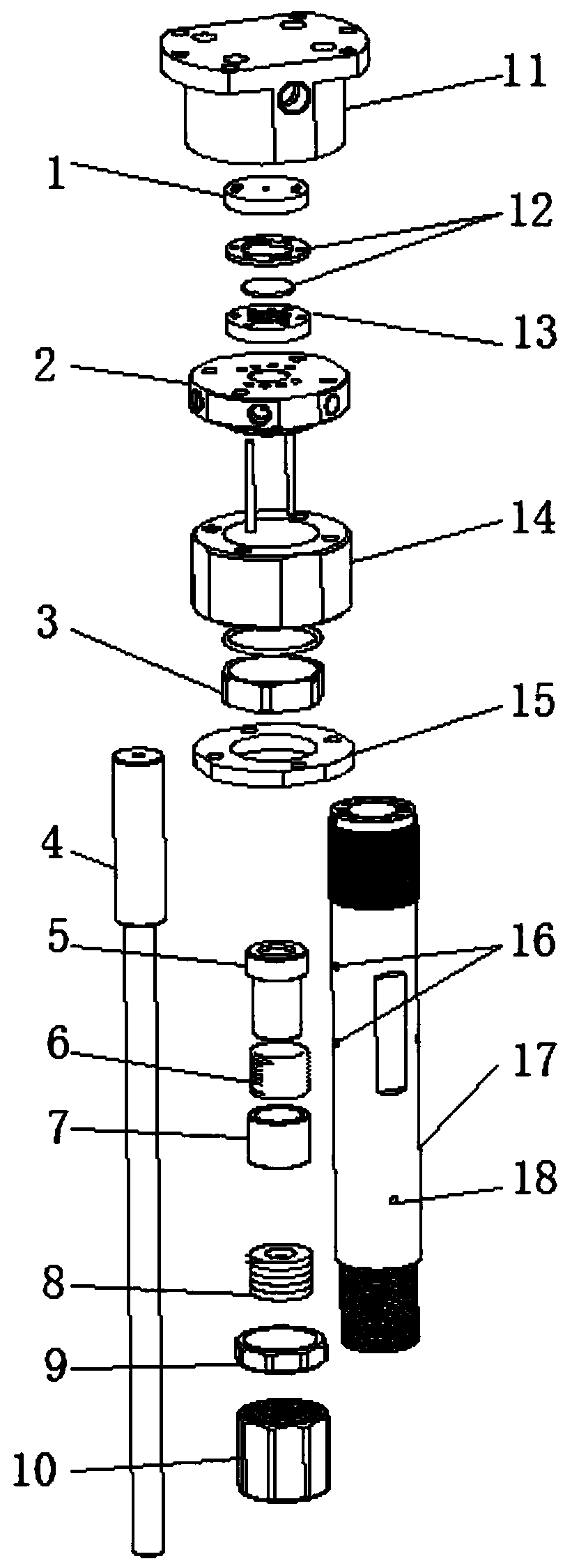
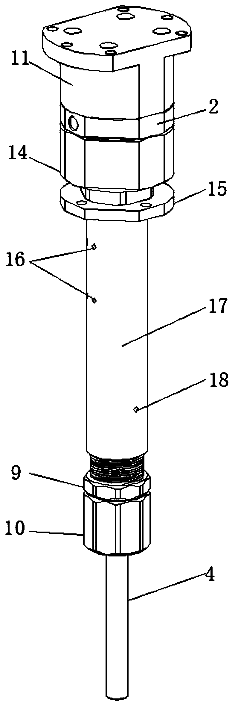
The invention discloses a pneumatic hammer for removing a cinder ladle, and belongs to the field of pneumatic hammers. The pneumatic hammer for the removing the cinder ladle comprises a cylinder barrel; a pneumatic hammer rod is arranged in the cylinder barrel in a sliding manner; an exhaust block and an air inlet block are sequentially connected to the upper end of the cylinder barrel; the upperend of the cylinder barrel is connected with the exhaust block and the air inlet block through a cylinder barrel connecting block; the pneumatic hammer further comprises an upper diaphragm, a movablediaphragm and a lower diaphragm; the upper diaphragm is fixedly arranged in the air inlet block; an air path a, an air path b and an air path c are arranged on the air inlet block, the upper diaphragm, the movable diaphragm, the lower diaphragm, the exhaust block and the cylinder barrel; the air path a is used for driving the pneumatic hammer rod to move upwards; the air path b is used for drivingthe pneumatic hammer rod to move downwards; and the movable diaphragm moves up and down by opening and closing the air path b. The quick pressure relief and the air path conversion are combined to perform reciprocating hitting, and the pneumatic hammer can quickly hit the cinder ladle, is large in hitting force, can quickly reset, and effectively avoids a sticking phenomenon.

Description

technical field [0001] The invention relates to the technical field of air hammers, in particular to a pneumatic hammer for slag removal. Background technique [0002] Die castings generally have multiple slag pockets that need to be cut at the beginning, and there are connecting sections between adjacent slag pockets. Generally, these slag pockets need to be removed. The existing slag pocket removal methods generally include manually knocking off die castings Slag bag, use a punch to wash off the die-casting slag bag, and use a profiling frame to take out the slag bag. However, knocking off the die-casting slag bag manually is labor-intensive, low in labor efficiency, high in cost, unstable in quality, and deformed; [0003] In the prior art, the application number is 201721215175.X, and a slag removal charter machine was disclosed on 2018.07.03, including a frame, a knocking plate is arranged on the frame, and an air hammer is arranged on the upper side of the knocking pla...

Claims


Application Information

Patent Timeline
Patent Type & Authority Applications(China)
IPC IPC(8): B22D17/20B22D31/00
CPCB22D17/2076
Inventor 钟健
Owner 肇庆谊龙科技有限公司
Learn More