
Metasurface color holography preparation method and optical system

An optical system and metasurface technology, applied in the field of color holographic imaging systems, can solve the problems of complex mechanical motion mechanism, fixed spatial frequency of light field, unfavorable optical path stability, etc., and achieve the effects of high efficiency, low cost, and easy structure preparation

Active Publication Date: 2020-01-17
SUZHOU UNIV
View PDF20 Cites 6 Cited by
  • Summary
  • Abstract
  • Description
  • Claims
  • Application Information

AI Technical Summary

Problems solved by technology

However, usually the spatial frequency of the structured light field output by the interference lithography system is fixed, and the structures are mainly periodic structures such as gratings and lattices, which cannot achieve real-time output of variable parameter pattern structures.
For example, the Institute of Microelectronics and Mechanics of National Taiwan University and AHEAD Light Spot Co., Ltd. jointly developed the Sparkle system, which uses a beam splitter and mirror splitting system. By changing the position of the lens, the two beams of light can form different sizes of focus on the photoresist plate. point, and rotating the entire optical prism group around the axis can change the orientation of the grating, and moving the two mirrors up and down can change the space frequency of the grating point, but its mechanical movement mechanism is complicated, which is not conducive to the stability of the optical path

Method used


Image

  • Metasurface color holography preparation method and optical system
  • Metasurface color holography preparation method and optical system
  • Metasurface color holography preparation method and optical system

Examples


Embodiment 1

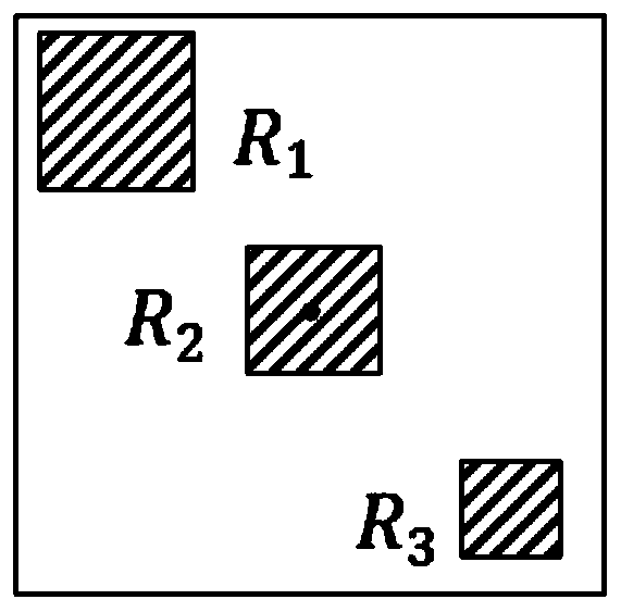
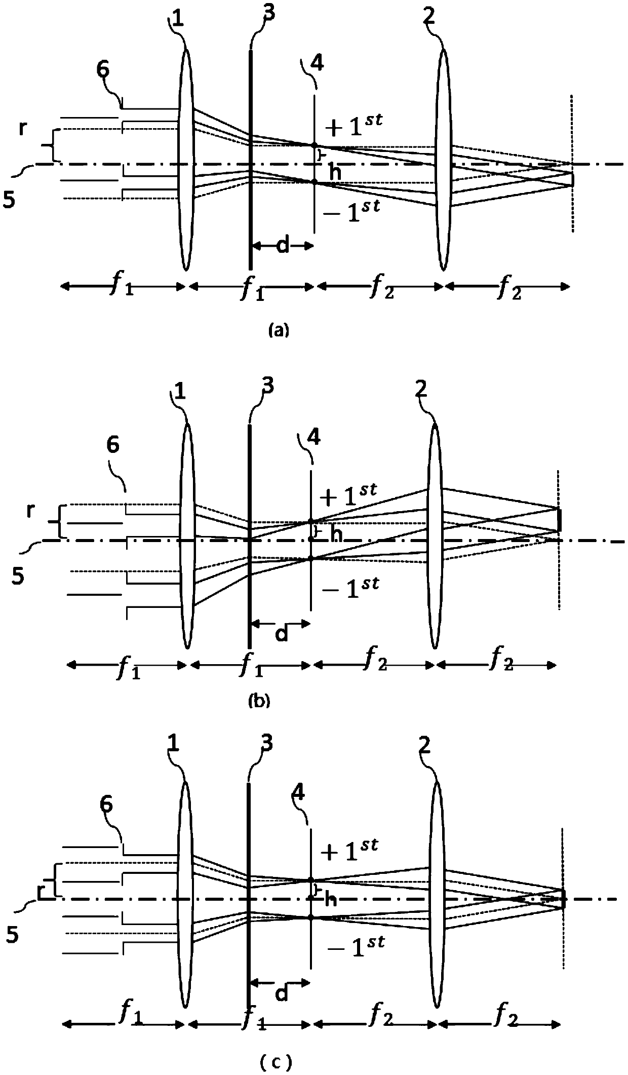
[0082] Example 1: Forming a metasurface color hologram with the same micro-nano structure and different pixel patterns on the back focal plane. Taking the R pixel as an example, its space frequency size and grating orientation are as follows: figure 1shown. The metasurface color hologram system used to prepare the R pixel target structure grating shown in this embodiment is as follows image 3 As shown in a, in a 4F optical system (focal lengths f1, f1, f2, f2, such as image 3 As shown), it includes a first lens (group) 1, a second lens (group) 2 and a light wave modulation unit, and the light wave modulation unit includes a phase grating 3 and a zero-order photomask 4, and the phase grating 3 is arranged on the second Between a lens (group) 1 and the zero-order photomask 4, the phase grating 3 can be shifted and / or rotated to realize the light field modulation of each wavelet, and the parameter can be adjusted on the back focal plane of the system The optical field distrib...

Embodiment 2

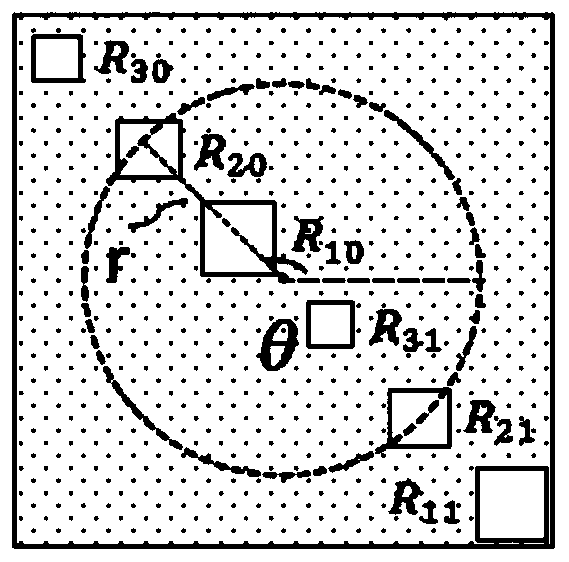
[0093] Embodiment 2: The same pixel pattern is formed on the back focal plane, and the target structure metasurface color hologram with different micro-nano structures is prepared, such as Figure 4 shown. The method of layered extraction of R, G, and B three-pixel target structures is used to obtain the preparation of metasurface color holograms, such as in order to obtain Figure 4 The target structure grating shown in the "Nine Palaces" is prepared by decomposing the target structure into R, G, and B three-pixel grating holograms, such as Figure 5 shown.

[0094] The metasurface color hologram used to prepare the pixel target structure grating shown in this embodiment is shown in Figure 3b, in a 4F optical system (focal length f1, f1, f2, f2), including the first lens (group) 1 , the second lens (group) 2 and the light-wave modulation unit, the light-wave modulation unit includes a phase grating 3 and a zero-order photomask 4, and the phase grating 3 is arranged on the f...

Embodiment 3

[0098] Embodiment 3: Different pixel patterns are formed on the back focal plane, and a metasurface color hologram with different micro-nano structure space frequency is prepared. The preparation of metasurface color holograms is obtained by layered extraction of R, G, and B three-pixel target structures, such as in order to obtain Figure 6 The target structure grating of the "nine-square grid" shown is prepared by decomposing the target structure into three-pixel holograms of R, G, and B, as shown in Figure 7 shown.

[0099] The metasurface color hologram used to prepare the pixel target structure grating shown in this embodiment is shown in Figure 3c, in a 4F optical system (focal length f1, f1, f2, f2), including the first lens (group) 1 , the second lens (group) 2 and the light-wave modulation unit, the light-wave modulation unit includes a phase grating 3 and a zero-order photomask 4, and the phase grating 3 is arranged on the first lens (group) 1 and the zero-order ph...


PUM


Abstract

The invention relates to a metasurface color holography preparation method, which comprises the following steps of on the basis of a pixel structure or pixel distribution, respectively layering and extracting a color target object image to obtain the corresponding multiple image layers; respectively obtaining a micro-nano structure and a micro-nano structure combination corresponding to each imagelayer, and obtaining a change relationship between the micro-nano structures and the micro-nano structure combinations among the layers; according to the combination of the micro-nano structure and aprimary color micro-nano structure of any image layer, realizing the simultaneous preparation of intra-layer multiple pixel micro-nano structures of the image layer by utilizing photoetching of spaceor / and phase modulation; and according to the change relationship of the micro-nano structures and the micro-nano structure combinations among the layers, realizing the simultaneous preparation of the micro-nano structures and the micro-nano structure combinations of the rest layers in a time-sharing manner by utilizing space or / and phase real-time regulation and control. According to the invention, the simultaneous preparation of multiple pixel micro-nano structures and the time-sharing preparation of the layered pixel combinations are realized, so that the large-format rapid preparation ofcolor holography can be realized.

Description

technical field [0001] The invention belongs to the technical field of color holographic imaging systems, and in particular relates to a method for preparing a supersurface color hologram and an optical system. Background technique [0002] Color holography is a method of digitally modulating and filtering the color separation hologram in the frequency domain by a computer to reproduce the object with the corresponding primary color light, and obtain the original true color object image after synthesis, and the obtained reproduction image can be very good Solve the problem of color crosstalk effectively and eliminate the influence of zero order and conjugate image. [0003] Due to the unique optical properties of functional materials with micro-nano structures, they have important research significance and application value in the fields of energy, new materials, and sensing. Therefore, methods for preparing such micro-nano structures emerge in endlessly. Commonly used meth...

Claims


Application Information

Patent Timeline
IPC IPC(8): G03H1/02
CPCG03H1/0276
Inventor 叶燕宋志叶红路畅王钦华陈林森
Owner SUZHOU UNIV
Learn More