
A three-dimensional camera sonar array signal receiver amplitude and phase correction device and method

An array signal and three-dimensional imaging technology, which is applied in the direction of measuring devices, sound wave reradiation, instruments, etc., can solve the problems of output maximum disturbance, low amplitude correction accuracy, and large measurement error, so as to improve phase correction accuracy and increase amplitude The effect of correcting accuracy and reducing influence

Active Publication Date: 2021-07-02
杭州瑞利海洋装备有限公司
View PDF13 Cites 0 Cited by
  • Summary
  • Abstract
  • Description
  • Claims
  • Application Information

AI Technical Summary

Problems solved by technology

However, due to the accuracy of the selected passive components, the performance difference of the active components, and the asymmetry of the printed board layout and wiring, the amplitude and phase of each channel of the receiver are inconsistent, so that the amplitude weight of each channel in the frequency domain beamforming process If the value and phase compensation value deviate from the theoretical design value, it may cause problems such as increased side lobe, decreased main lobe gain, and beam pointing deviation, which will reduce the imaging quality of the system and affect the identification and observation of underwater targets.
[0003] There are few studies on the amplitude and phase correction method of the receiver of the three-dimensional camera sonar array signal. For reference, the receiver amplitude and phase correction method in the field of phased radar is used to correct the phase by using two orthogonal signals of the reference channel to maximize the output The value is used as the amplitude for amplitude correction. When the phase error is close to the integer multiple of π / 2, the measurement error introduced is relatively large. Due to circuit noise interference, there is disturbance in the maximum output value, and the amplitude correction accuracy is low.

Method used


Image

  • A three-dimensional camera sonar array signal receiver amplitude and phase correction device and method
  • A three-dimensional camera sonar array signal receiver amplitude and phase correction device and method
  • A three-dimensional camera sonar array signal receiver amplitude and phase correction device and method

Examples


Embodiment Construction

[0039] The present invention will be further elaborated and illustrated below in conjunction with the accompanying drawings and specific embodiments. The technical features of the various implementations in the present invention can be combined accordingly on the premise that there is no conflict with each other.

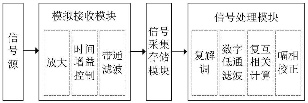
[0040] Such as figure 1 As shown, it is a schematic block diagram of the structure of the amplitude and phase correction device applicable to the three-dimensional camera sonar array signal receiver in the present invention, and its main modules include a signal source, an analog receiving module, a signal acquisition and storage module, and a signal processing module. The function of each module and the specific working process are described in detail below.

[0041] The signal source is used to simultaneously input in-phase signals with the same amplitude and the frequency of the sonar working frequency to each channel of the analog receiving module when performi...


PUM


Abstract

The invention discloses an amplitude and phase correction device and method suitable for a three-dimensional camera sonar array signal receiver. The device mainly includes a signal source, an analog receiving module, a signal acquisition and storage module, and a signal processing module; it is characterized in that when the amplitude and phase correction is performed on the three-dimensional camera sonar array signal receiver, the signal source is input at the same time in each channel of the analog receiving module. , the frequency is the in-phase signal of the sonar operating frequency; the analog receiving module amplifies the signal with low noise, time gain control, and band-pass filter processing, and outputs it to the signal acquisition storage module; the signal acquisition storage module A / D samples and converts it into a digital signal And store the sampling data; the signal processing module reads the sampling data, performs complex demodulation, and digital low-pass filtering. By calculating the effective value of each channel data, the amplitude difference between different receiving channels and the reference channel is obtained. The phase difference between the channel and the reference channel, and compensate for the amplitude and phase difference.

Description

technical field [0001] The invention belongs to the field of sonar array signal processing, in particular to a method for correcting amplitude and phase consistency of a sonar array signal receiver. Background technique [0002] The 3D camera sonar uses a rectangular area array containing thousands of array elements and arranged at equal intervals to receive echo signals, and obtains high-resolution underwater 3D images through frequency-domain beamforming algorithms and real-time image processing technology. The frequency-domain beamforming algorithm uses uniform weights, and performs fast Fourier transform on the time-domain signals of each array element, and extracts the same frequency components for phase compensation. However, due to the accuracy of the selected passive components, the performance difference of the active components, and the asymmetry of the printed board layout and wiring, the amplitude and phase of each channel of the receiver are inconsistent, so tha...

Claims


Application Information

Patent Timeline
Patent Type & Authority Patents(China)
IPC IPC(8): G01S7/52G01S15/89
CPCG01S7/52004G01S15/89
Inventor 彭阳明方斯喆赵伟昌陈文渊周志新刁庆伟冯宏郭冉杭亮韩礼波
Owner 杭州瑞利海洋装备有限公司
Learn More