
Rock/mineral wool centrifugal machine and method for producing rock/mineral wool using rock/mineral wool centrifugal machine

A centrifuge and mineral wool technology, applied in glass manufacturing equipment, manufacturing tools, etc., can solve the problems of limiting rock/mineral wool output and quality, limiting rock/mineral wool fiber formation rate, and many slag balls, etc., to achieve a breakthrough output The upper limit, the improvement of product quality, and the effect of less slag balls

Pending Publication Date: 2020-01-17
CHANGZHOU YINGLAI MACHINERY
View PDF0 Cites 0 Cited by
  • Summary
  • Abstract
  • Description
  • Claims
  • Application Information

AI Technical Summary

Problems solved by technology

Since only two rollers are used for fiber formation, this arrangement and diameter design limit the fiber formation rate of rock / mineral wool, and there are more slag balls, which limits the output and quality of rock / mineral wool, making the current The maximum output of rock / mineral wool can only reach 4 tons / hour, and no breakthrough can be made

Method used


Image

  • Rock/mineral wool centrifugal machine and method for producing rock/mineral wool using rock/mineral wool centrifugal machine
  • Rock/mineral wool centrifugal machine and method for producing rock/mineral wool using rock/mineral wool centrifugal machine

Examples


Embodiment 1

[0026] In order to make the purpose, technical solutions and advantages of the embodiments of the present invention clearer, the technical solutions in the embodiments of the present invention will be clearly and completely described below in conjunction with the drawings in the embodiments of the present invention. Obviously, the described embodiments It is a part of embodiments of the present invention, but not all embodiments. The components of the embodiments of the invention generally described and illustrated in the figures herein may be arranged and designed in a variety of different configurations.

[0027] Accordingly, the following detailed description of the embodiments of the invention provided in the accompanying drawings is not intended to limit the scope of the claimed invention, but merely represents selected embodiments of the invention. Based on the embodiments of the present invention, all other embodiments obtained by persons of ordinary skill in the art wi...

Embodiment 2

[0042] This embodiment is basically the same as Embodiment 1, the difference is that: the axis of the first roller 1 is used as the origin to establish a coordinate system, the axis coordinates of the second roller 2 are (300mm ± 50mm, -10mm ± 50mm), the first The axis coordinates of the third roller 3 are (70mm±50mm, -340mm±50mm), and the axis coordinates of the fourth roller 4 are (430mm±50mm, -480mm±50mm).

[0043] Compared with Embodiment 1, the positions of the four centrifugal rollers in this embodiment are the mirror images of the four centrifugal rollers in the embodiment.


PUM


Abstract

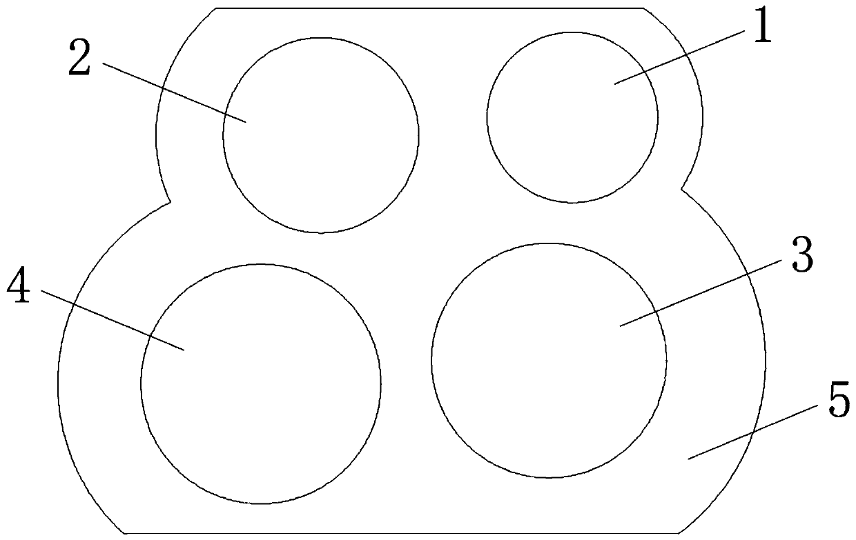
The invention relates to a rock / mineral wool centrifugal machine and a rock / mineral wool production method thereof. The rock / mineral wool centrifugal machine comprises a machine base and four centrifugal rollers arranged on the machine base; the four centrifugal rollers are respectively a first roller, a second roller, a third roller and a fourth roller; wherein the second roller is located on oneside of the first roller, and the height difference between the axis of the second roller and the axis of the first roller ranges from -60 mm to 40 mm; the third roller is located below the first roller, and the axis of the third roller deviates towards the side close to the second roller; the height difference between the axis of the second roller and the axis of the first roller ranges from -60mm to 40 mm; the third roller is located below the first roller, and the axis of the third roller deviates towards one side close to the second roller; so that fibers can be formed by the four centrifugal rollers, few slag balls are generated in the production process, and the fiber forming rate of the rock / mineral wool centrifugal machine is greatly increased.

Description

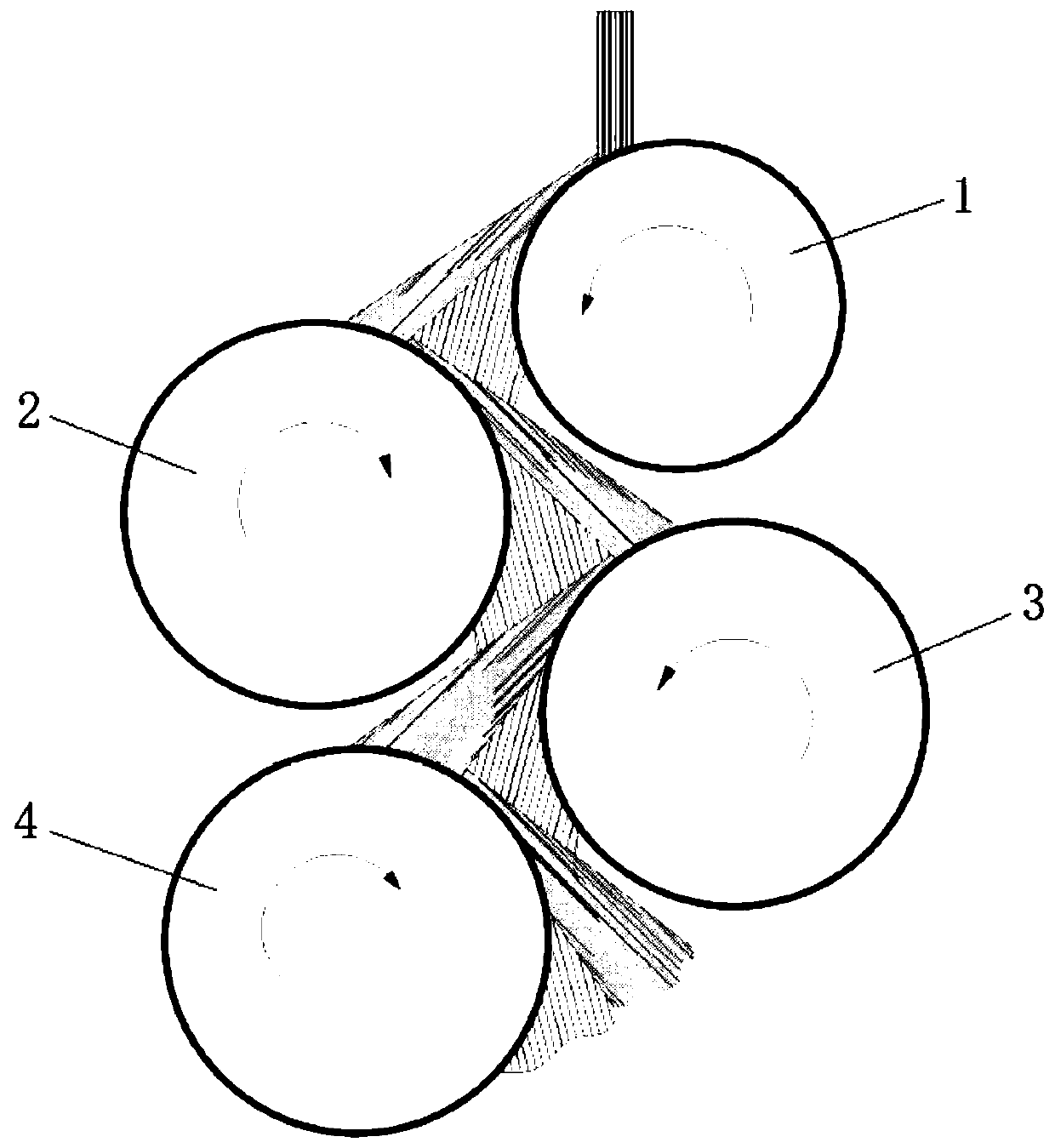
technical field [0001] The invention relates to a rock / mineral wool centrifuge and a method for producing rock / mineral wool. Background technique [0002] At present, rock / mineral wool is widely used as insulation material for building walls, and rock / mineral wool fiber forming equipment is an important equipment that determines the output and quality of rock / mineral wool. The four-roller fiber-forming centrifuge is currently the most used rock / mineral wool fiber-forming equipment on the market. It has four centrifugal rollers, such as figure 1 As shown, the four centrifugal rolls are respectively the first roll 1, the second roll 2, the third roll 3 and the fourth roll 4, and the diameter of the traditional centrifugal rolls is 180-230 mm, wherein the first roll 1 is the receiving roll , used to accept the melt; the second roll 2 is located under the side of the first roll 1, and the height difference exceeds 110mm, used for guiding, so that the melt is thrown onto the thi...

Claims


Application Information

Patent Timeline
Patent Type & Authority Applications(China)
IPC IPC(8): C03B37/04C03C13/06
CPCC03B37/04C03C13/06
Inventor 曹磊潘建橹
Owner CHANGZHOU YINGLAI MACHINERY
Learn More