
Antenna device

An antenna device and antenna element technology, which is applied to antennas, antenna supports/installation devices, resonant antennas, etc., can solve the problems of difficult adjustment of antenna performance, high interference between inductive elements and antenna elements, and difficult control of capacitance distance. achieve the effect of reducing the size

Pending Publication Date: 2020-01-14
昆山展腾电子科技有限公司
View PDF0 Cites 0 Cited by
  • Summary
  • Abstract
  • Description
  • Claims
  • Application Information

AI Technical Summary

Problems solved by technology

[0005] However, since there is a distance between the inductive element and the antenna element, and the capacitive coupling is used to the antenna element, the capacitance and the above-mentioned distance are difficult to control. In addition to interference, it may also cause antenna performance to be difficult to adjust
Moreover, the overall antenna length is still relatively long, making it more difficult to install in a miniaturized wireless terminal

Method used


Image

  • Antenna device
  • Antenna device

Examples


Embodiment Construction

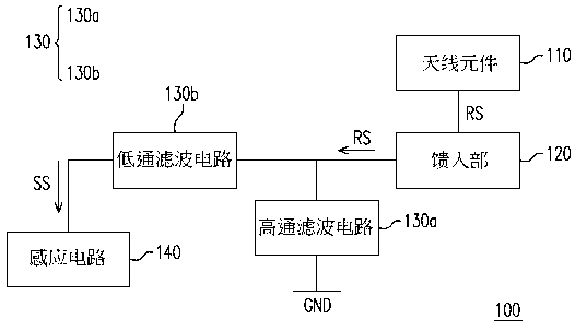
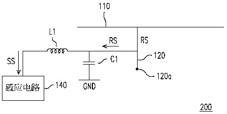
[0034] Please refer to figure 1 , which is a schematic diagram of an antenna device according to an embodiment of the present invention. In this embodiment, the antenna device 100 includes an antenna element 119 , a feeding portion 120 , a filter circuit 130 and a sensing circuit 140 . The antenna element 110 receives or transmits a radiation signal RS, wherein the radiation signal RS includes at least one of a first component and a second component, and the frequency band of the first component is lower than the frequency band of the second component. In different embodiments, the antenna element 110 may be a planar inverted F antenna (PIFA) or an appropriate antenna selected by a designer according to requirements, but the present invention is not limited thereto. In addition, the above-mentioned first component may be a fundamental frequency component in the radiation signal RS, and the above-mentioned second component may be a radio frequency component in the radiation si...


PUM


Abstract

The disclosure provides an antenna device including an antenna element, a feeding portion, a filtering circuit, and a sensing circuit. The antenna element transmits or receives a radiation signal, wherein the radiation signal includes at least one of a first component and a second component, and a frequency band of the first component is lower than a frequency band of the second component. The feeding portion is coupled to the antenna element. The filtering circuit is coupled to the feeding portion, receives the radiation signal via the feeding portion and filters the second component of the radiation signal to generate a sensing signal. The sensing circuit is coupled to the filtering circuit, receives the sensing signal and determines whether a human body approaches the antenna device based on the sensing signal.

Description

technical field [0001] The present invention relates to an antenna device, and in particular to an antenna device in which a single antenna element has both radiating signal and sensing functions. Background technique [0002] With the rapid development of wireless communication technology, wireless terminals such as smart phones have been widely used, and their size is gradually moving towards the direction of miniaturization. However, while the size of the wireless terminal is miniaturized, in addition to increasing the difficulty of related structural design, the electromagnetic radiation of the wireless terminal to the human body will also be correspondingly enhanced. [0003] At present, an index for measuring the electromagnetic radiation of an antenna to a human body is a specific absorption rate (specific absorption rate, SAR), which refers to an electromagnetic wave energy absorption ratio of a wireless terminal. The specific meaning of SAR is: under the action of ...

Claims


Application Information

Patent Timeline
Patent Type & Authority Applications(China)
IPC IPC(8): H01Q23/00H01Q1/50H01Q1/24H01Q1/22
CPCH01Q1/22H01Q1/242H01Q1/50H01Q23/00G01R29/0814H01Q1/245H01Q1/44H01Q5/328H01Q5/335H01Q9/0421G01R29/10H01Q1/24H01Q1/36H01Q5/20H01Q9/045
Inventor 曾义伟
Owner 昆山展腾电子科技有限公司
Learn More