
rotary compressor

A technology of rotary compressor and rotary shaft, which is applied in the direction of rotary piston machinery, rotary piston pump, rotary piston type/oscillating piston type pump components, etc., can solve the problems of refrigerant leakage and refrigerant leakage, and achieve Effect of improving efficiency and lowering temperature

Active Publication Date: 2022-03-15
LG ELECTRONICS INC
View PDF0 Cites 0 Cited by
  • Summary
  • Abstract
  • Description
  • Claims
  • Application Information

AI Technical Summary

Problems solved by technology

However, in this case, there is a high possibility of refrigerant leakage between the discharge chamber and the oil storage space, and a high possibility of refrigerant leakage through the discharge chamber.

Method used


Image

  • rotary compressor
  • rotary compressor
  • rotary compressor

Examples


Embodiment Construction

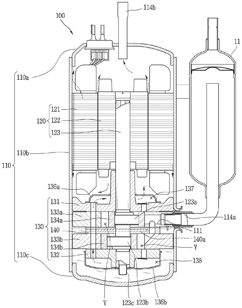
[0036] Hereinafter, the hermetic compressor according to the present invention will be described in detail with reference to the drawings.

[0037] A singular expression in this specification includes a plural expression unless a different meaning is clearly stated in the text.

[0038] In the process of describing the embodiments disclosed in the present invention, if it is judged that the specific description of related known technologies hinders the understanding of the embodiments of the present invention, the detailed description will be omitted.

[0039] The accompanying drawings are only to help understand the embodiments disclosed in this specification, and the technical ideas disclosed in this specification are not limited by the accompanying drawings. It should be understood that the present invention includes the ideas of the present invention and all changes, equivalents and substitutes within the technical scope.

[0040] figure 1 It is a sectional view showing t...


PUM


Abstract

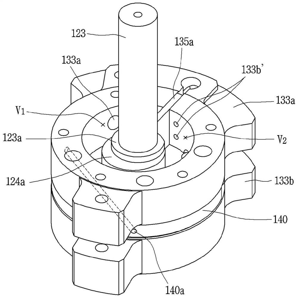
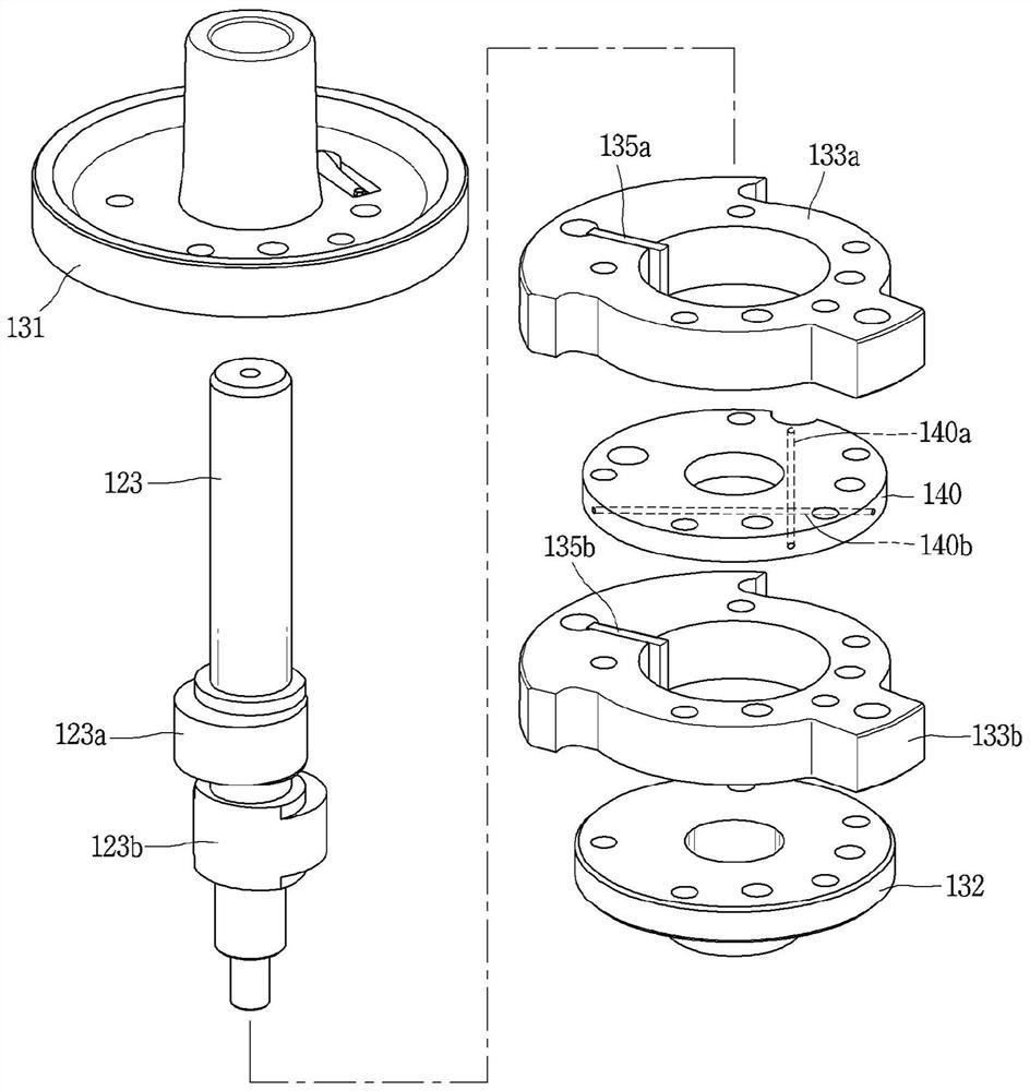
The invention relates to a rotary compression chamber, comprising: a driving motor and a rotating shaft, the driving motor is arranged inside the housing, and the rotating shaft is combined with the driving motor to transmit rotational force; a first cylinder and a second cylinder The cylinder has a compression space formed in the circular center of the opening; the first roller and the second roller revolve in the compression space; the first vane and the second vane divide the compression space of each cylinder into suction chamber and compression chamber; a main bearing coupled to the upper portion of the first cylinder and a sub-bearing coupled to the lower portion of the second cylinder; and an intermediate plate disposed on the main Between the bearing and the sub-bearing, the first cylinder and the second cylinder are separated; the middle plate is formed with an oil flow path formed from one side toward the inside, passing along the oil flow path The moving oil undergoes heat exchange.

Description

technical field [0001] The present invention relates to a hermetic compressor, and particularly to a rotary compressor capable of lowering the temperature of a compression unit. Background technique [0002] As a vapor compression refrigeration cycle device suitable for such as a refrigerator or an air conditioner, a compressor can be divided into a rotary type and a reciprocating type according to the way the compressor compresses the refrigerant. [0003] The rotary compressor is a way to make the volume of the compression space variable by rolling the piston (hereinafter referred to as the roller) in the cylinder to rotate or revolve, and the reciprocating compressor is to make the compression space by the reciprocating motion of the roller in the cylinder. variable volume. [0004] As a rotary compressor, there is a rotary compressor that compresses refrigerant using the rotational force of a transmission unit. [0005] In recent years, gradually miniaturizing rotary c...

Claims


Application Information

Patent Timeline
Patent Type & Authority Patents(China)
IPC IPC(8): F04C18/356F04C28/22F04C29/02F04C29/04
CPCF04C18/356F04C28/22F04C29/02F04C29/04F04C29/028
Inventor 曹国铉史范东
Owner LG ELECTRONICS INC
Learn More