Fan

A fan and rotor technology, applied in the field of household appliances, can solve the problems of inability to realize dual-axis dual-power or dual-degree-of-freedom control, increase the axial length of the motor, weight and cost, service life, and damage to structural stability, and improve safety. The effect of stability and reliability, low noise and high reliability

Pending Publication Date: 2020-01-10
GUANGDONG WELLING ELECTRIC MACHINE MFG +1
View PDF0 Cites 3 Cited by
  • Summary
  • Abstract
  • Description
  • Claims
  • Application Information

AI Technical Summary

Problems solved by technology

[0002] Fans in the related art are often used in fan coil units, air conditioners, heaters, cooling fans, centrifuges, wind power generation, range hoods, blowers, air purifiers, etc., and their structures include fan blades and motors. During use, they are found as follows Disadvantages: The dual-shaft technology in the existing fan actually consists of the shaft of a single motor protruding from both ends to form shafts on both sides, but a single motor can only drive the fan blades to rotate at the same speed or in the same direction, and cannot realize dual-axis in the true sense. Shaft dual-power or dual-degree-of-freedom control; the dual-power or multi-power technology in the existing fan is actually two or more motors outputting double or multiple speeds through axial series, which increases the axial length of the motor, Weight and cost; for some applications, the speed of a single fan blade of the fan is required to reach 1200rpm, the performance requirements of the motor are relatively strict, and the cost is high. The motor is in a high-load working state for a long time, which will affect its service life and structural stability. certain damage

Method used


Image

  • Fan
  • Fan
  • Fan

Examples


Embodiment Construction

[0041] In order to understand the above-mentioned purpose, features and advantages of the present invention more clearly, the present invention will be further described in detail below in conjunction with the accompanying drawings and specific embodiments. It should be noted that, in the case of no conflict, the embodiments of the present application and the features in the embodiments can be combined with each other.

[0042] In the following description, many specific details are set forth in order to fully understand the present invention. However, the present invention can also be implemented in other ways different from those described here. Therefore, the protection scope of the present invention is not limited by the specific details disclosed below. EXAMPLE LIMITATIONS.

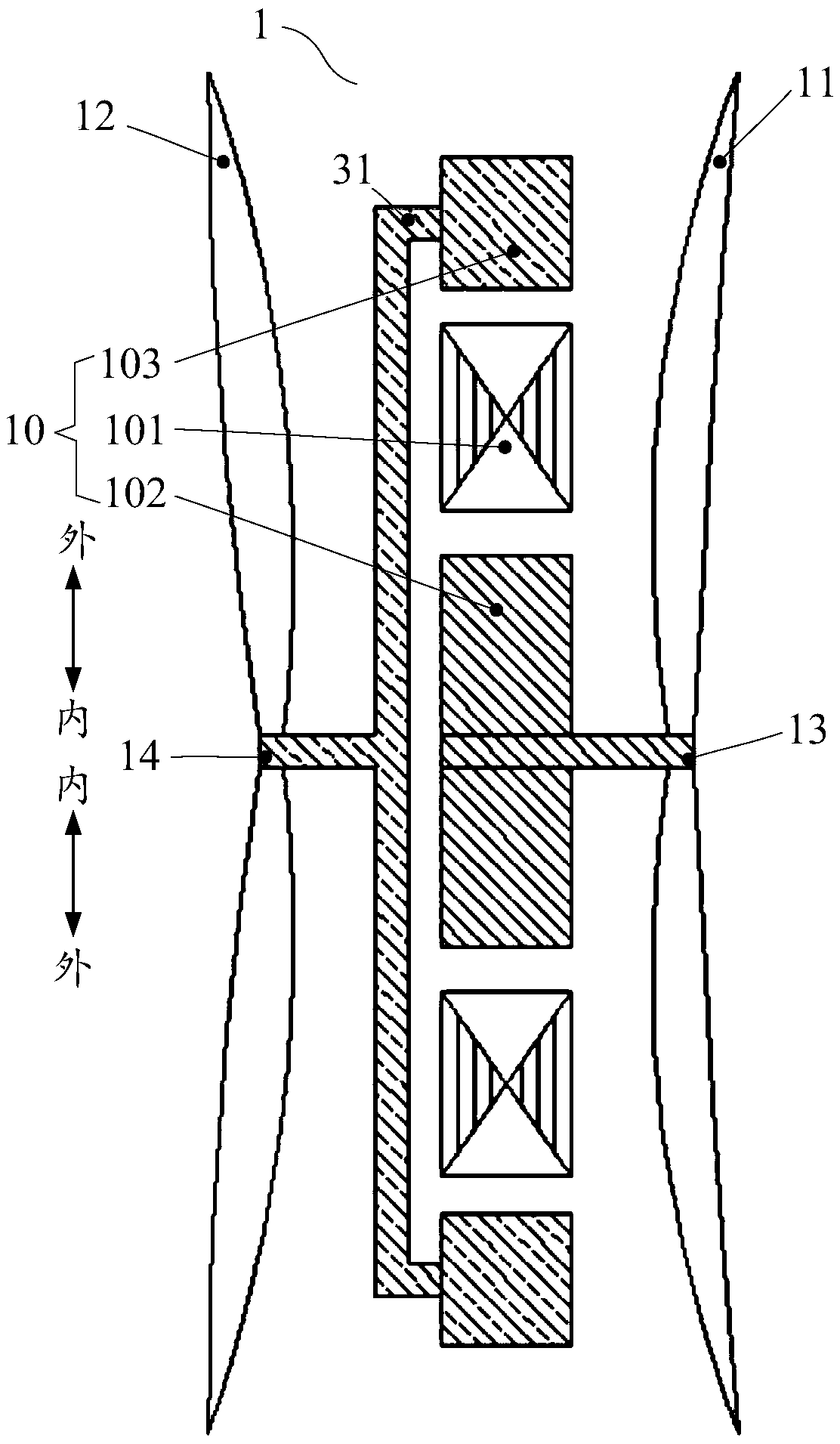
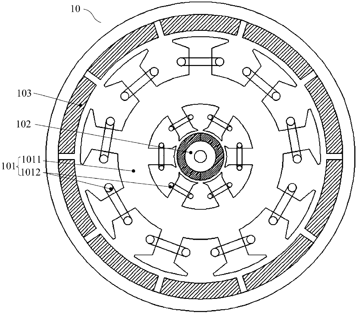
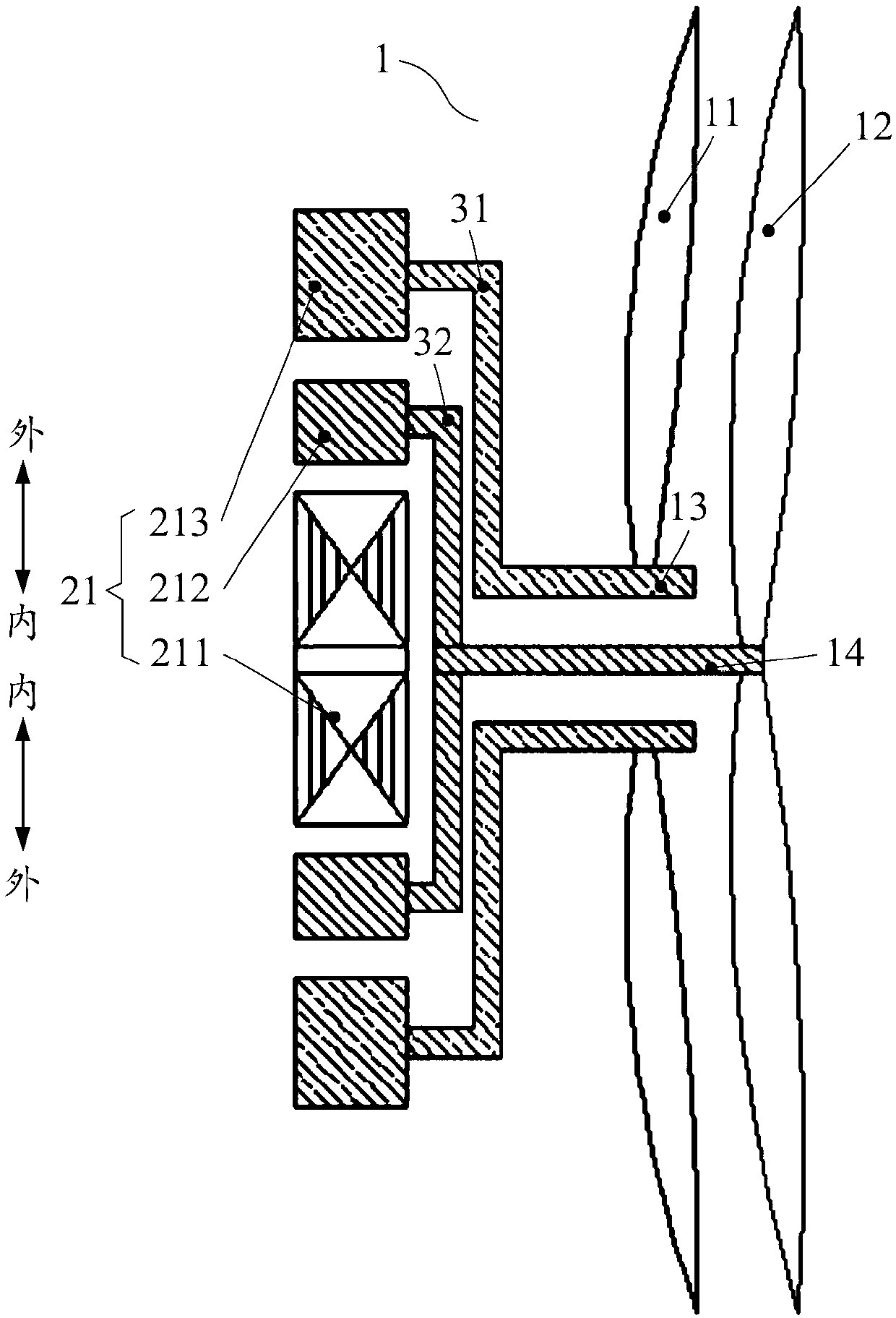
[0043] Refer below Figure 1 to Figure 6 Fans according to some embodiments of the invention are described.

[0044] Such as Figure 1 to Figure 6 As shown, a fan 1 provided according to some embo...


PUM


Abstract

The invention provides a fan. The fan comprises a motor, a first rotating shaft, a second rotating shaft, a first fan blade and a second fan blade; the motor comprises a stator, a first rotor and a second rotor which are mutually nested and can mutually rotate, and the first rotor and the second rotor mutually and independently rotate; the stator comprises a stator iron core and a stator winding wound on the stator iron core, and the first rotor and the second rotor are used for driving the first rotating shaft provided with the first fan blade and the second rotating shaft provided with the second fan blade to concentrically rotate correspondingly; and particularly, the first rotor is a reluctance rotor, the second rotor is a permanent magnet rotor, and the stator, the reluctance rotor and the permanent magnet rotor are sequentially nested from inside to outside or from outside to inside. According to the fan provided by the invention, dual-shaft dual-power rotation is achieved in themodes without mechanical differential speed and separation and reunion, the system integration degree is high, the power density is large, energy consumption is low, reliability is high, and noise issmall.

Description

technical field [0001] The invention relates to the technical field of household appliances, in particular to a fan. Background technique [0002] Fans in the related art are often used in fan coil units, air conditioners, heaters, cooling fans, centrifuges, wind power generation, range hoods, blowers, air purifiers, etc., and their structures include fan blades and motors. During use, they are found as follows Disadvantages: The dual-shaft technology in the existing fan actually consists of the shaft of a single motor protruding from both ends to form shafts on both sides, but a single motor can only drive the fan blades to rotate at the same speed or in the same direction, and cannot realize dual-axis in the true sense. Shaft dual-power or dual-degree-of-freedom control; the dual-power or multi-power technology in the existing fan is actually two or more motors outputting double or multiple speeds through axial series, which increases the axial length of the motor, Weight...

Claims


Application Information

Patent Timeline
IPC IPC(8): F04D25/08F04D25/16F04D29/32H02K1/22H02K1/27H02K3/04H02K7/14H02K16/02
CPCF04D25/0606F04D25/0633F04D25/064F04D25/0646F04D25/08F04D25/166F04D29/325H02K1/22H02K1/27H02K3/04H02K7/14H02K16/02H02K2213/03F04D25/16F04D29/00F04D29/32
Inventor 吴迪武谷雨陈金涛龚黎明诸自强
Owner GUANGDONG WELLING ELECTRIC MACHINE MFG
Why Eureka
Try Eureka