Rare earth treatment device

A processing device and rare earth technology, applied in the direction of electrolysis process, surface etching composition, electrolysis components, etc., can solve the problems of excessive electric energy, increase of production cost, failure to recycle fluorine gas, etc., and achieve the goal of reducing efficiency and increasing production cost Effect

Active Publication Date: 2020-01-10
包头市金为达稀土材料有限公司
View PDF9 Cites 1 Cited by
  • Summary
  • Abstract
  • Description
  • Claims
  • Application Information

AI Technical Summary

Problems solved by technology

[0004] In order to overcome the problem of using the existing neodymium metal treatment device, the present invention must use complex methods to separate the metal neodymium remaining in the crucible from other auxiliary electrolysis raw materials, which consumes a lot of time and sets more equipment, which increases the production cost; When preparing metal neodymium, the raw material neodymium oxide is very easy to combine with water in the air, and it is very difficult to separate the bound water after short-term drying. Neodymium oxide containing bound water will greatly reduce the efficiency of electrolysis, consume more electric energy, and improve the efficiency of electrolysis. Production cost; when preparing metal neodymium, the fluorine element in the auxiliary electrolytic raw material lithium fluoride and neodymium fluoride will be emitted in the form of fluorine gas, which is highly corrosive, but it is also a resource that can be recycled. Traditional preparation equipment Due to the lack of recycling devices, the disadvantage of being unable to recycle fluorine gas, the technical problem to be solved by the present invention is to provide a rare earth processing device

Method used


Image

  • Rare earth treatment device
  • Rare earth treatment device
  • Rare earth treatment device

Examples


Embodiment

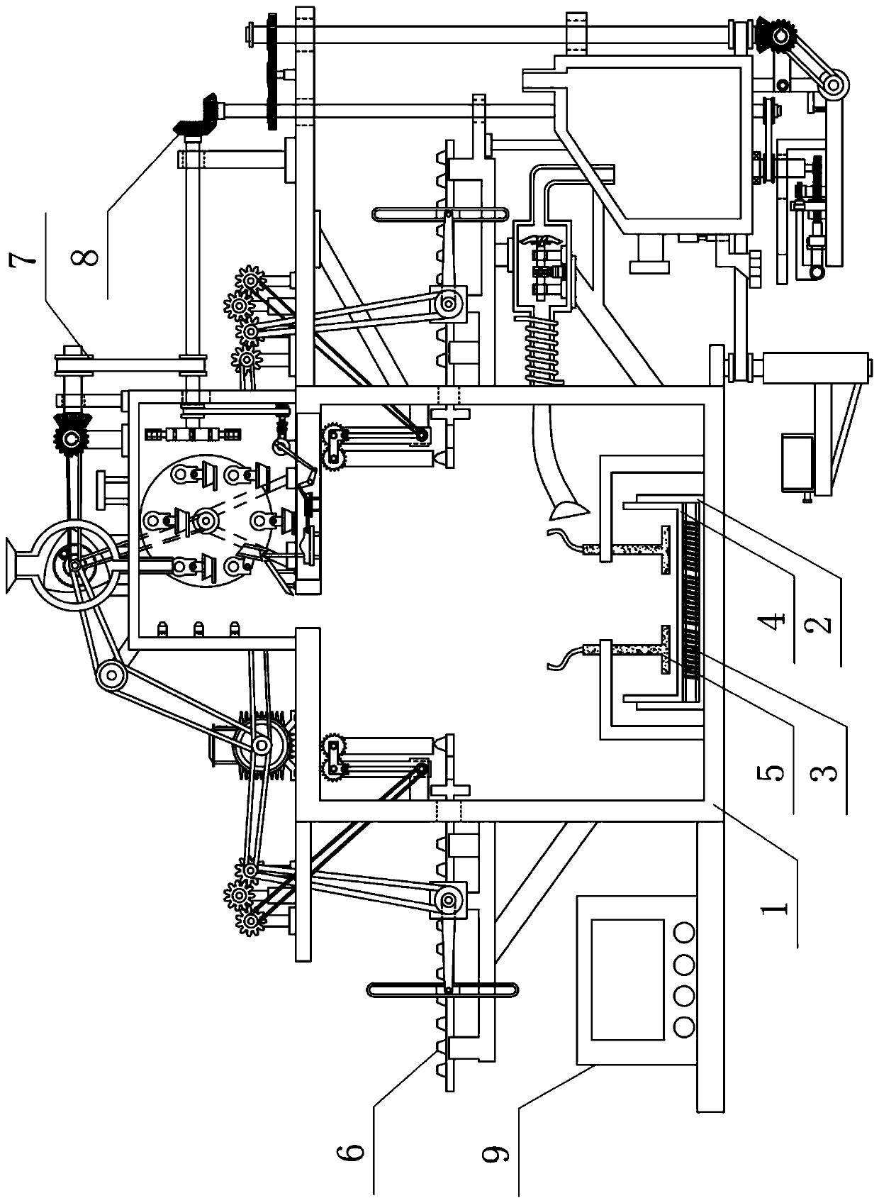
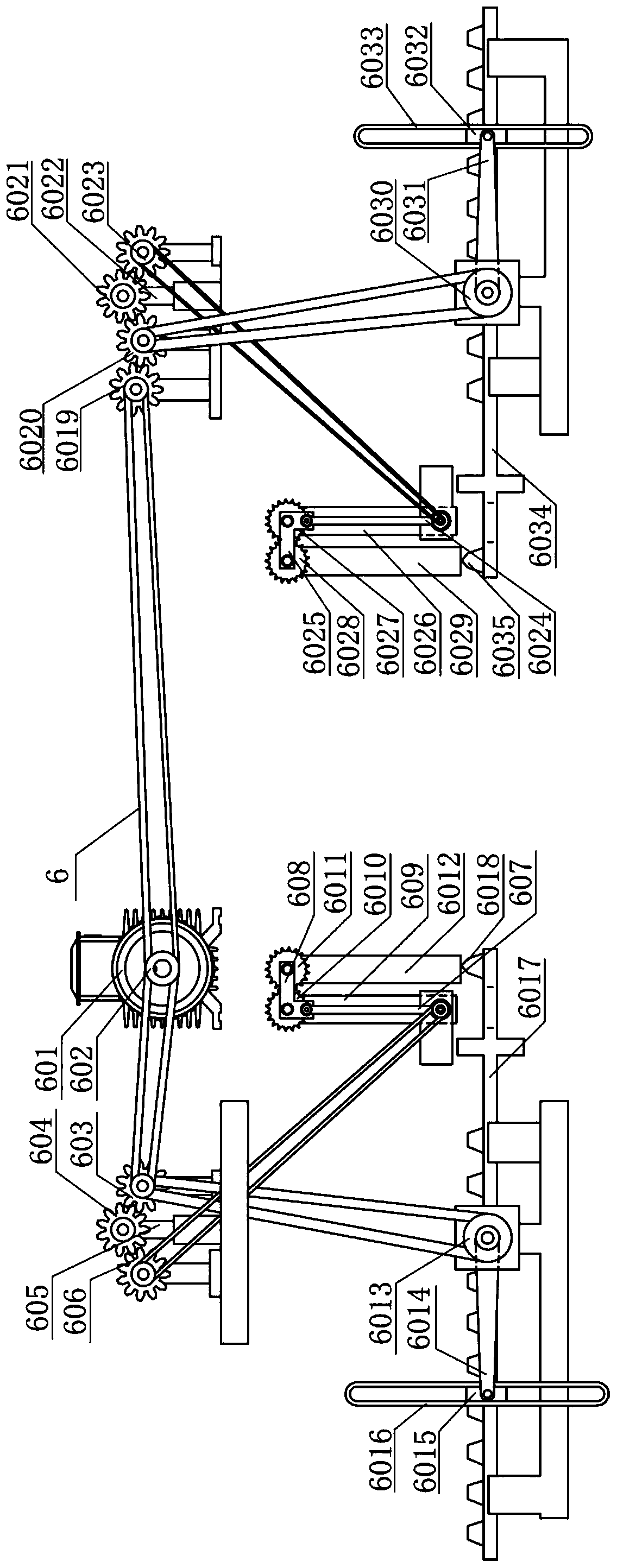
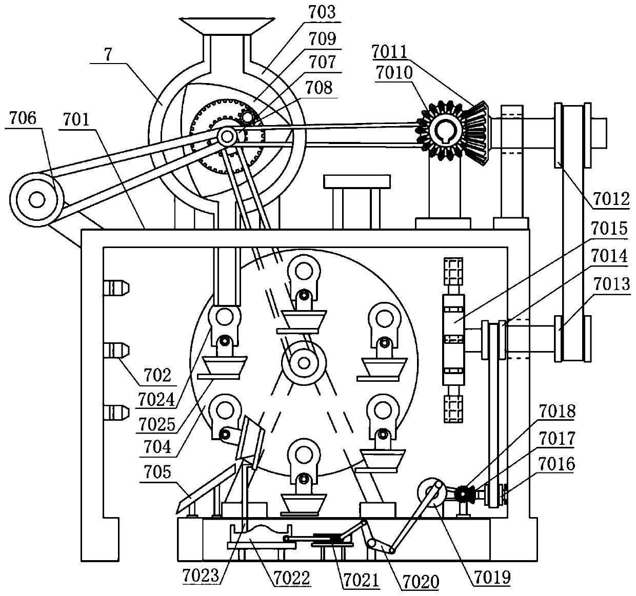
[0025] A rare earth processing device, such as Figure 1-6 As shown, it includes electrolysis chamber 1, heat insulation crucible 2, heating wire 3, electrolysis crucible 4, electrode 5, condensation separation device 6, high temperature purification device 7, fluorine gas recovery device 8 and control panel 9; the middle part of the inner bottom of electrolysis chamber 1 It is connected with the heat-insulated crucible 2; the left top of the electrolysis chamber 1 is provided with a condensation separation device 6; the top of the electrolysis chamber 1 is provided with a high-temperature purification device 7, and the left end of the high-temperature purification device 7 is connected with the condensation separation device 6; There is a fluorine gas recovery device 8, and the top of the fluorine gas recovery device 8 is connected to the high-temperature purification device 7; the left bottom of the electrolysis chamber 1 is provided with a control panel 9; the middle part of...


PUM

PropertyMeasurementUnit
melting pointaaaaaaaaaa
densityaaaaaaaaaa

Abstract

The invention relates to a treatment device, and particularly relates to a rare earth treatment device. The technical problem to be solved is to provide the rare earth treatment device. The rare earthtreatment device comprises a heat insulation crucible, an electrolysis crucible, electrodes, a condensation separation device, a high-temperature purification device and a fluorine gas recovery device, wherein the high-temperature purification device is arranged at the top end of an electrolysis chamber, and the left end of the high-temperature purification device is connected with the condensation separation device; and the fluorine gas recovery device is arranged at the right end of the electrolysis chamber. The rare earth treatment device aims at solving the problem that the metal neodymium residual in the crucible after electrolysis is separated from other auxiliary electrolytic raw materials through a complex method when an existing neodymium metal treatment device is in use, and a large amount of time is consumed. The rare earth treatment device achieves the effects of thoroughly drying crystal water through a " friction wheel " slow-speed rotation, recovering fluorine gas fromoutside to prepare hydrofluoric acid for glass etching, finally recovering the auxiliary raw materials, protecting the device and creating additional value.

Description

technical field [0001] The invention relates to a processing device, in particular to a rare earth processing device. Background technique [0002] Neodymium is a silver-white metal with a melting point of 1024°C and a density of 7.004g / ㎝ 3 , are paramagnetic. Neodymium is one of the most active rare earth metals, which can quickly darken in the air and form oxides; it reacts slowly in cold water and reacts rapidly in hot water. Neodymium-doped yttrium aluminum garnet and neodymium glass can replace ruby ​​as laser materials, and neodymium and praseodymium glass can be used as goggles. With the birth of praseodymium element, neodymium element also came into being. The arrival of neodymium element has activated the rare earth field, played an important role in the rare earth field, and controlled the rare earth market. One of the existing industrial methods of refining neodymium is the electrolytic ternary mixture of neodymium oxide, neodymium fluoride and lithium fluoride...

Claims


Application Information

Patent Timeline
Patent Type & Authority Applications(China)
IPC IPC(8): C22B7/00C22B59/00C25C3/34C25C7/06C03C15/00C09K13/08
CPCC03C15/00C09K13/08C22B7/001C22B59/00C25C3/34C25C7/06
Inventor 陈芳平
Owner 包头市金为达稀土材料有限公司
Why Eureka
Try Eureka