Machine tool based on image tool setting

A technology of image pairing and machine tools, which is applied in the direction of metal processing machinery parts, automatic control devices, measuring/indicating equipment, etc., can solve the problems of affecting production efficiency, long time, and many steps of tool setting, so as to improve production efficiency and reduce the cost of tool setting. Knife steps, save the effect of tool setting time

Inactive Publication Date: 2020-01-10
贵州宝康智能装备有限公司
View PDF9 Cites 1 Cited by
  • Summary
  • Abstract
  • Description
  • Claims
  • Application Information

AI Technical Summary

Problems solved by technology

When the existing machine tools are used for tool setting, it is necessary to drive the tool up and down to make multiple contact with the workpiece to achieve tool setting. There are many steps for tool setting and the time is long, which affects production efficiency.

Method used


Image

  • Machine tool based on image tool setting
  • Machine tool based on image tool setting
  • Machine tool based on image tool setting

Examples


Embodiment Construction

[0015] The specific embodiments of the present invention will be further described below in conjunction with the accompanying drawings. It should be noted here that the descriptions of these embodiments are used to help understand the present invention, but are not intended to limit the present invention. In addition, the technical features involved in the various embodiments of the present invention described below may be combined with each other as long as they do not constitute a conflict with each other.

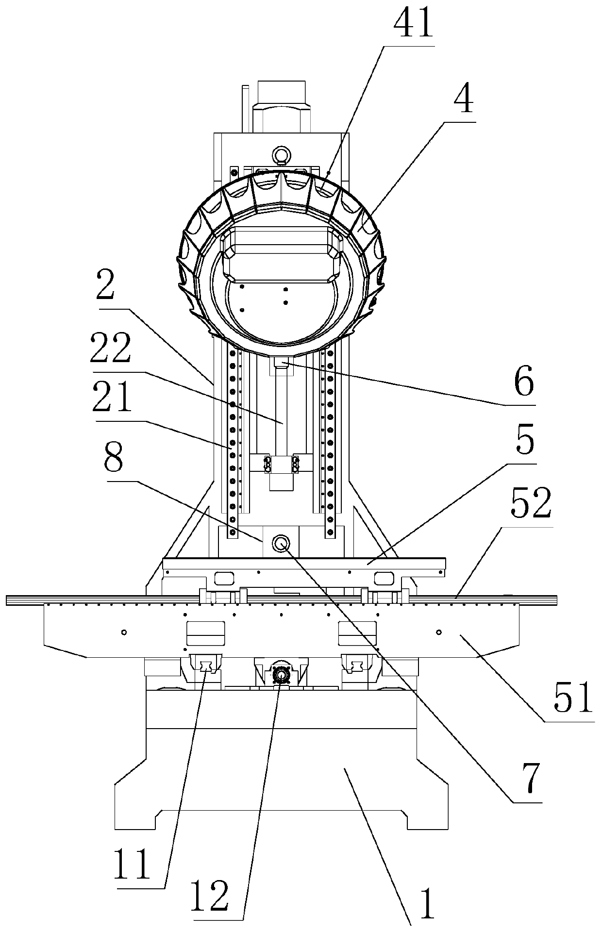
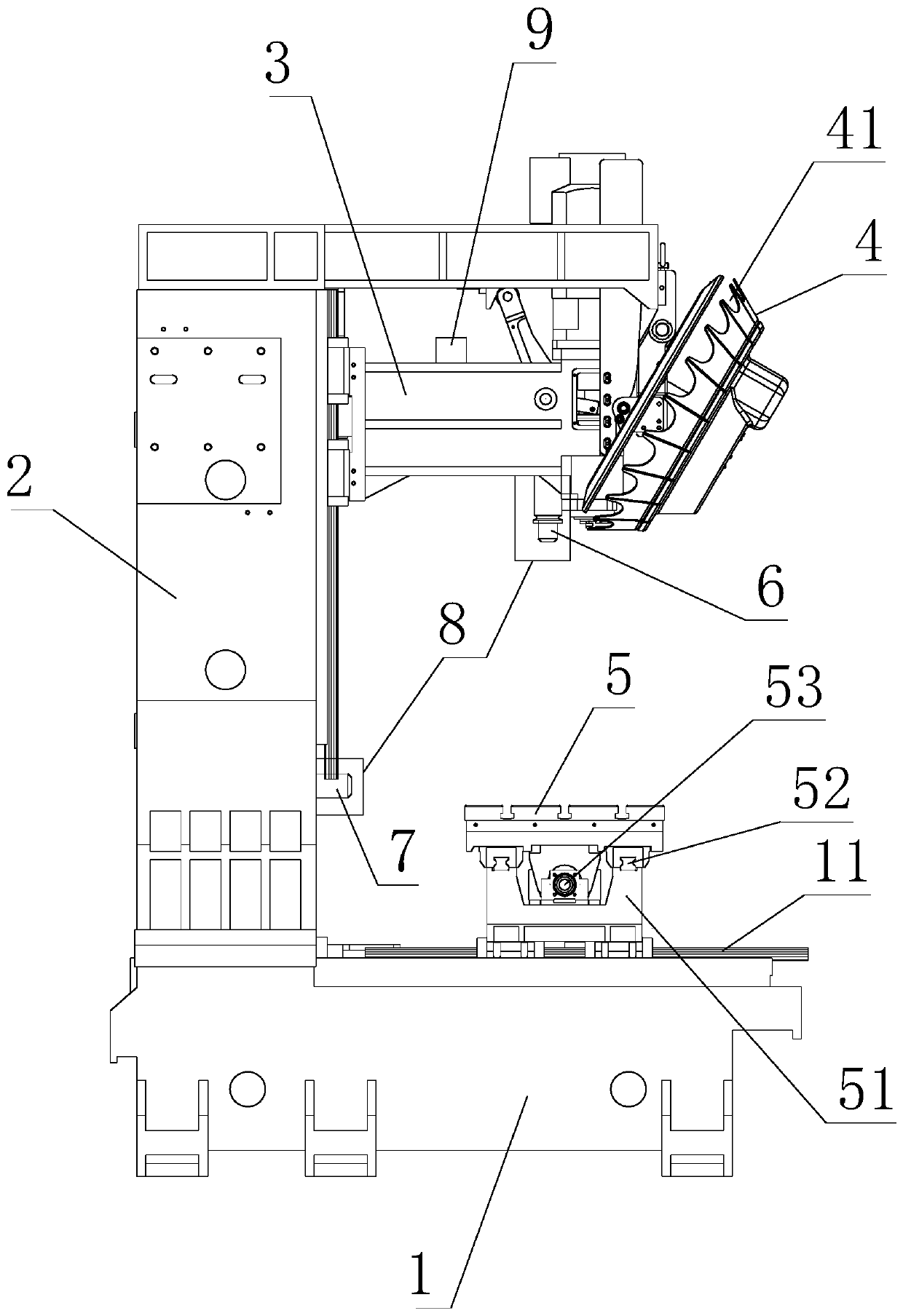
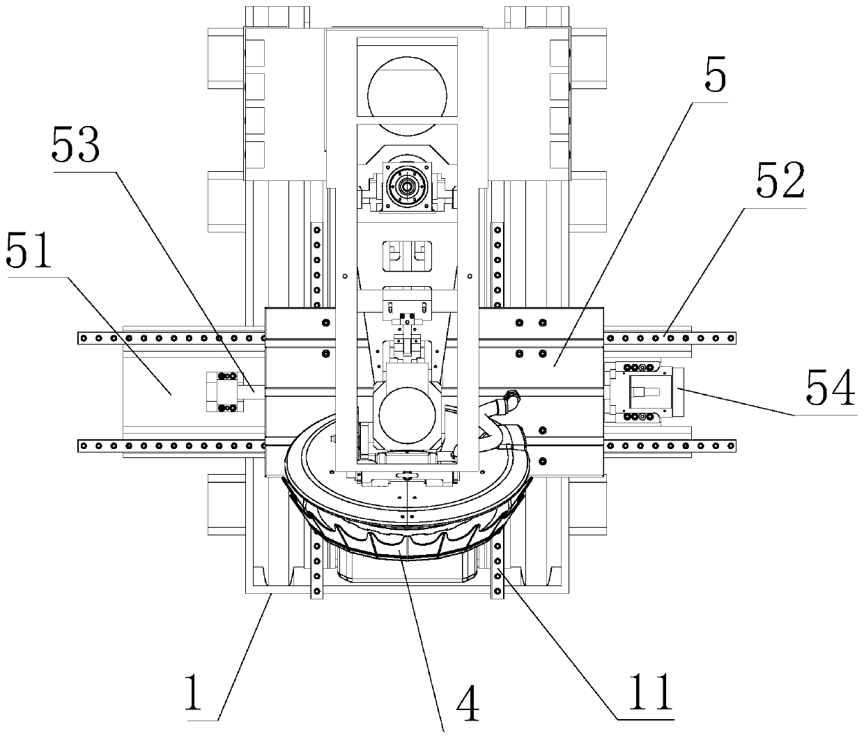
[0016] refer to Figure 1-3 , a machine tool based on image tool setting, including a bed 1, a column 2, a control system, and a spindle box 3 that can move up and down on the column 2, and the end of the spindle box 3 is provided with a tool holder and an automatic tool changer Disk 4, the bed 1 is provided with a workbench 5 that can move horizontally and vertically, and the main camera 6 is provided on the lower side of the headstock 3, and the signal of the main cam...


PUM


Abstract

The invention discloses a machine tool based on image tool setting. The machine tool comprises a bed, a column, a control system and a spindle box which can move up and down on the column, wherein theend part of the spindle box is provided with a tool clamp and an automatic tool change plate, the bed is provided with a workbench which can move horizontally and vertically, the lower side of the spindle box is provided with a main camera, the main camera is connected to the control system through signals, the control system comprises a storage, high angle shot size comparison sample data, a tool setting analysis program and a machining program, the main camera takes images of workpieces fixed on the workbench and transmits the pictures to the storage, and the tool setting analysis program compares the information of the images taken by the main camera with the high angle shot size comparison sample data to determine the position and size information of the workpieces. According to the machine tool based on image tool setting, the main camera is arranged at the lower side of the spindle box, the spindle box can complete the tool setting at the original position, and the tool settingcan be carried out without up and down action of the automatic tool change plate, so that the tool setting steps are reduced, the tool setting time is saved and the production efficiency is improved.

Description

technical field [0001] The invention relates to the field of machine tools, in particular to an image-based tool setting machine tool. Background technique [0002] A machine tool refers to a machine that uses various cutting or non-cutting methods to process metal or non-metallic raw materials into the required shape or size by using appropriate tools, or for the purpose of adding more precise processing. When the existing machine tools are used for tool setting, it is necessary to drive the tool up and down to contact the workpiece multiple times to realize the tool setting. There are many steps for tool setting and the time is long, which affects the production efficiency. Therefore, it is necessary to improve and optimize the existing technology. Contents of the invention [0003] The technical problem to be solved by the invention is how to reduce the tool setting steps and the tool setting time. [0004] In order to solve the problems of the technologies described ...

Claims


Application Information

Patent Timeline
Patent Type & Authority Applications(China)
IPC IPC(8): B23Q17/22B23Q15/24B23Q15/22
CPCB23Q15/22B23Q15/24B23Q17/22B23Q17/2233
Inventor 胡胜庚胡胜贤
Owner 贵州宝康智能装备有限公司
Why Eureka
Try Eureka