Submarine air foam fire extinguishing system

An air foam and fire extinguishing system technology, which is applied in the field of air foam fire extinguishing systems for boats, can solve problems such as easy fracture, low shape retention effect, and low foam stability, so as to avoid fouling, excellent fire extinguishing effect, and facilitate operation and maintenance. The effect of overhaul

Active Publication Date: 2020-01-07
九江中船长安消防设备有限公司
View PDF7 Cites 5 Cited by
  • Summary
  • Abstract
  • Description
  • Claims
  • Application Information

AI Technical Summary

Problems solved by technology

However, the stability of the foam formed by the existing air foam fire extinguishing system is not high, and the shape retention effect is not high under a certain flow length, and it is easy to break. Therefore, it is imminent to design a fire extinguishing system with high stability foam

Method used


Image

  • Submarine air foam fire extinguishing system
  • Submarine air foam fire extinguishing system
  • Submarine air foam fire extinguishing system

Examples


Embodiment 1

[0028] like figure 1 Shown, a kind of boat air foam fire extinguishing system comprises air foam meter 1, air foam storage tank 2, discharge funnel 26 and water supply equipment 3 and high-pressure air supply equipment 4, and described air foam meter 1 and described air The foam storage tanks 2 are connected by a foaming agent pipeline 21, and a fresh water pipeline 5 is provided between the water supply equipment 3 and the air foam storage tank 2;

[0029] The high-pressure air supply equipment 4 is connected to the air foam storage tank 2 by setting a high-pressure air pipeline 11, and the high-pressure air pipeline 11 is sequentially provided with a pressure gauge valve 10, a pressure reducing valve 8, and a safety alarm valve 9 along the air supply direction;

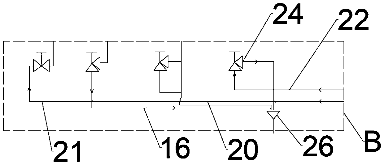
[0030] The air foam storage tank 2 is provided with an air foam pipeline 27, the air foam pipeline 27 is connected with the main pipe 12, and the connection is provided with a right-angle stop check valve 24; There...

Embodiment 2

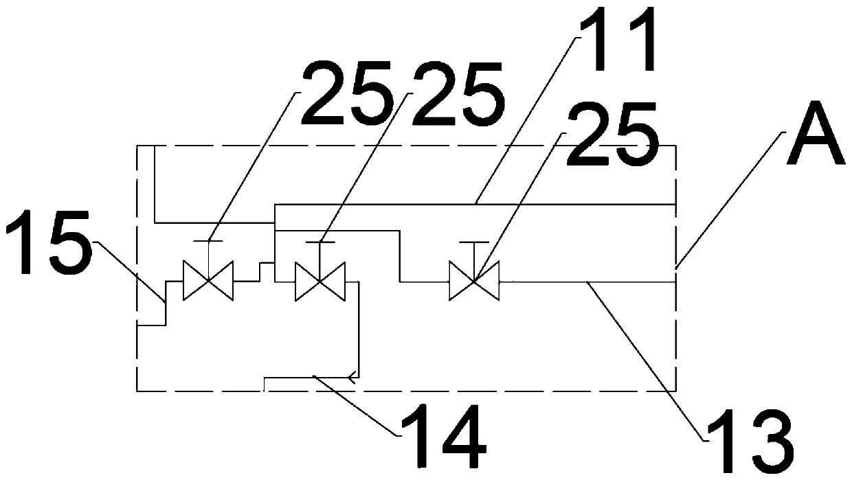
[0033] This embodiment is a further optimization made on the basis of Embodiment 1. Specifically, the high-pressure air pipeline 11 located behind the safety alarm valve 9 along the air supply direction is provided with a first branch vent pipe 13, a second branch vent pipe The air pipe 14 , the third branch air pipe 15 , the first branch air pipe 13 is connected to the feeding port of the air foam meter 1 .

Embodiment 3

[0035] This embodiment is a further optimization made on the basis of Embodiment 2. Specifically, the air foam meter 1 is also provided with an air outlet pipeline 22, and the air outlet pipeline 22 is connected with the discharge funnel 26. On the air outlet pipeline 22 A right-angle cut-off check valve 24 is provided.


PUM


Abstract

The invention discloses a submarine air foam fire extinguishing system. The submarine air foam fire extinguishing system comprises an air foam batchmeter, an air foam storage tank, a discharge funnel,a water supply device and a high-pressure air supply device. The air foam batchmeter is connected with the air foam storage tank through a foaming agent pipe. A fresh water pipe is arranged between the water supply device and the air foam storage tank. The high-pressure air supply device is connected with the air foam storage tank through a high-pressure air pipe. The high-pressure air pipe is provided with a pressure gauge valve, a pressure reducing valve and a security alarm valve in the air supply direction in sequence. The air foam storage tank is provided with an air foam pipe. The air foam pipe is connected with a header pipe. A right-angle stop check valve is arranged at the joint between the air foam pipe and the header pipe. The air foam pipe is provided with a throttling casingpipe and a net-like diffuser in the delivery direction in sequence. The tail end of the header pipe is connected with a coiling block bracket. The coiling block bracket is used for storing a adhesiveplaster hose with a diffusion nozzle in each cabin of a submarine. Formed air mechanical foam has high stability and can be maintained for 1-1.5 h.

Description

technical field [0001] The invention relates to the field of fire fighting equipment, in particular to an air foam fire extinguishing system for boats. Background technique [0002] At present, the fire extinguishing systems commonly used on boats include water-based fire extinguishing systems, foam fire extinguishing systems, dry powder fire extinguishing systems, halogenated hydrocarbon fire extinguishing systems and other new fire extinguishing systems, among which foam fire extinguishing systems are divided into chemical foam fire extinguishing and air foam fire extinguishing systems; The foam fire extinguishing system uses a certain amount of air foam liquid, water and air to form tiny dense film-like bubble groups filled with air through mechanical or hydraulic impact, so as to achieve the fire extinguishing effect. However, the foam formed by the existing air foam fire extinguishing system is not stable, and the shape retention effect is not high under the condition o...

Claims


Application Information

Patent Timeline
IPC IPC(8): A62C3/10A62C5/02A62C31/02A62C33/02A62C33/06A62C35/68A62C37/50
CPCA62C3/10A62C5/024A62C31/02A62C33/02A62C33/06A62C35/68A62C37/50
Inventor 张岩高旭辉叶刚肖志强
Owner 九江中船长安消防设备有限公司
Why Eureka
Try Eureka