
Power coil with built-in cooling structure

A technology of power coils and cooling structures, which is applied in the direction of transformers/inductor coils/windings/connections, circuits, electrical components, etc., which can solve the problems of easy water and electricity safety, poor air cooling and heat dissipation of excitation power coils, etc., and improve heat conduction Efficacy, simple structure, and the effect of increasing the contact area

Pending Publication Date: 2020-01-03
YAXIN (HUAIHUA) ELECTRONICS CO LTD
View PDF0 Cites 2 Cited by
  • Summary
  • Abstract
  • Description
  • Claims
  • Application Information

AI Technical Summary

Problems solved by technology

[0005] The purpose of the present invention is to propose a power coil with a built-in cooling structure in order to solve the problem that the excitation power coil has a poor heat dissipation effect through air cooling and that water and electricity safety is likely to occur when cold water is used to pass through the hollow wire.

Method used


Image

  • Power coil with built-in cooling structure
  • Power coil with built-in cooling structure
  • Power coil with built-in cooling structure

Examples


Embodiment Construction

[0029] The following will clearly and completely describe the technical solutions in the embodiments of the present invention with reference to the accompanying drawings in the embodiments of the present invention. Obviously, the described embodiments are only some, not all, embodiments of the present invention. Based on the embodiments of the present invention, all other embodiments obtained by persons of ordinary skill in the art without creative efforts fall within the protection scope of the present invention.

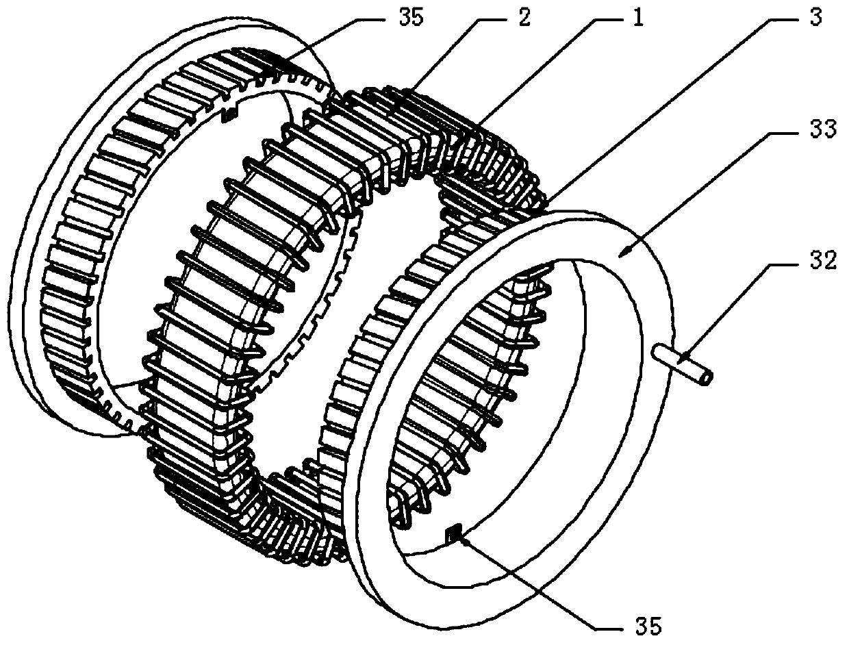
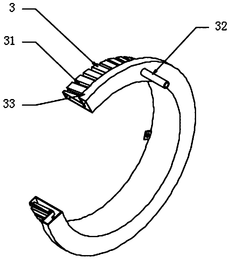
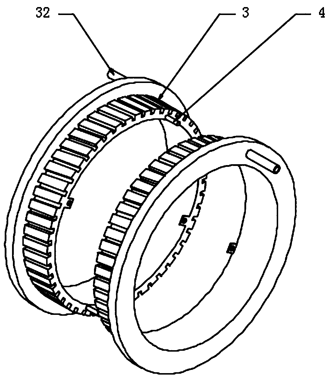
[0030] see Figure 1-5 , the present invention provides a technical solution: a power supply coil with a built-in cooling structure, including an annular iron core 1 and a coil 2 wound on the annular iron core 1, and also includes two heat-dissipating rings sleeved at both ends of the annular iron core 1 Sleeve 3, the outer wall of the heat-dissipating annular sleeve 3 is provided with a groove 31 in the direction of the teeth of the helical gear, and the outer wal...


PUM


Abstract

The invention discloses a power supply coil with a built-in cooling structure. The power supply coil comprises an annular iron core and a winding coil wound on the annular iron core, and further comprises two annular heat dissipation sleeves sleeved at two ends of the annular iron core, and grooves with helical gear teeth are formed in the outer surface walls of the annular heat dissipation sleeves. The winding coil wound on the annular iron core is distributed at intervals, the two ends of the annular iron core are sleeved with the two annular heat dissipation sleeves, the grooves are formedin the outer surface walls of the annular heat dissipation sleeves, the winding wire of the winding coil is clamped into the grooves, so when the two annular heat dissipation sleeves and the winding coil are mounted, the two annular heat dissipation sleeves only need to be oppositely inserted from two sides of the winding coil and then rotate reversely, and buckling connection of the two annular heat dissipation sleeves is achieved by means of guiding of the winding coil, so the spliced heat dissipation sleeves are convenient to install and detach, the contact area of the heat dissipation sleeves with the winding coil is increased, and the heat conduction effect is improved.

Description

technical field [0001] The invention relates to the technical field of heat dissipation of excitation power supply coils, in particular to a power supply coil with a built-in cooling structure. Background technique [0002] The excitation coil will generate heat under the action of strong current. The cooling methods currently used include air cooling and water cooling. Water-cooled excitation coils are generally wound with hollow wires. A fan is used to cool the excitation coil to ensure the normal working performance of the excitation coil winding. [0003] However, for the water-cooled structure, since cooling water needs to be passed into the hollow wire, if a slight leakage occurs, it will affect the safety of the water-electric connection of the water-cooled excitation coil. [0004] Therefore, the present invention provides a power coil with a built-in cooling structure. Contents of the invention [0005] The purpose of the present invention is to propose a power ...

Claims


Application Information

Patent Timeline
IPC IPC(8): H01F27/28
CPCH01F27/2876
Inventor 张青山
Owner YAXIN (HUAIHUA) ELECTRONICS CO LTD
Learn More