Eureka AIR delivers breakthrough ideas for toughest innovation challenges, trusted by R&D personnel around the world.

Adhesive tape blanking device for copper foil adhesive tape production

A tape and copper foil technology, applied in metal processing and other directions, can solve the problems of low safety performance, easy accidental injury to staff, inconvenient to replace the punching head, etc., to achieve good sealing effect, save punching time, and speed up punching. The effect of the adjudication process

Inactive Publication Date: 2020-01-03
湖北富和冠电子材料有限公司
View PDF0 Cites 3 Cited by
  • Summary
  • Abstract
  • Description
  • Claims
  • Application Information

AI Technical Summary

Problems solved by technology

[0004] The existing copper foil tape punching device is inconvenient to replace the punching head, and the punching head is generally directly exposed to the external environment, which is easily corroded by the surrounding environment, and it is easy to accidentally injure the staff, and the safety performance is low

Method used


Image

  • Adhesive tape blanking device for copper foil adhesive tape production
  • Adhesive tape blanking device for copper foil adhesive tape production
  • Adhesive tape blanking device for copper foil adhesive tape production

Examples


Embodiment 1

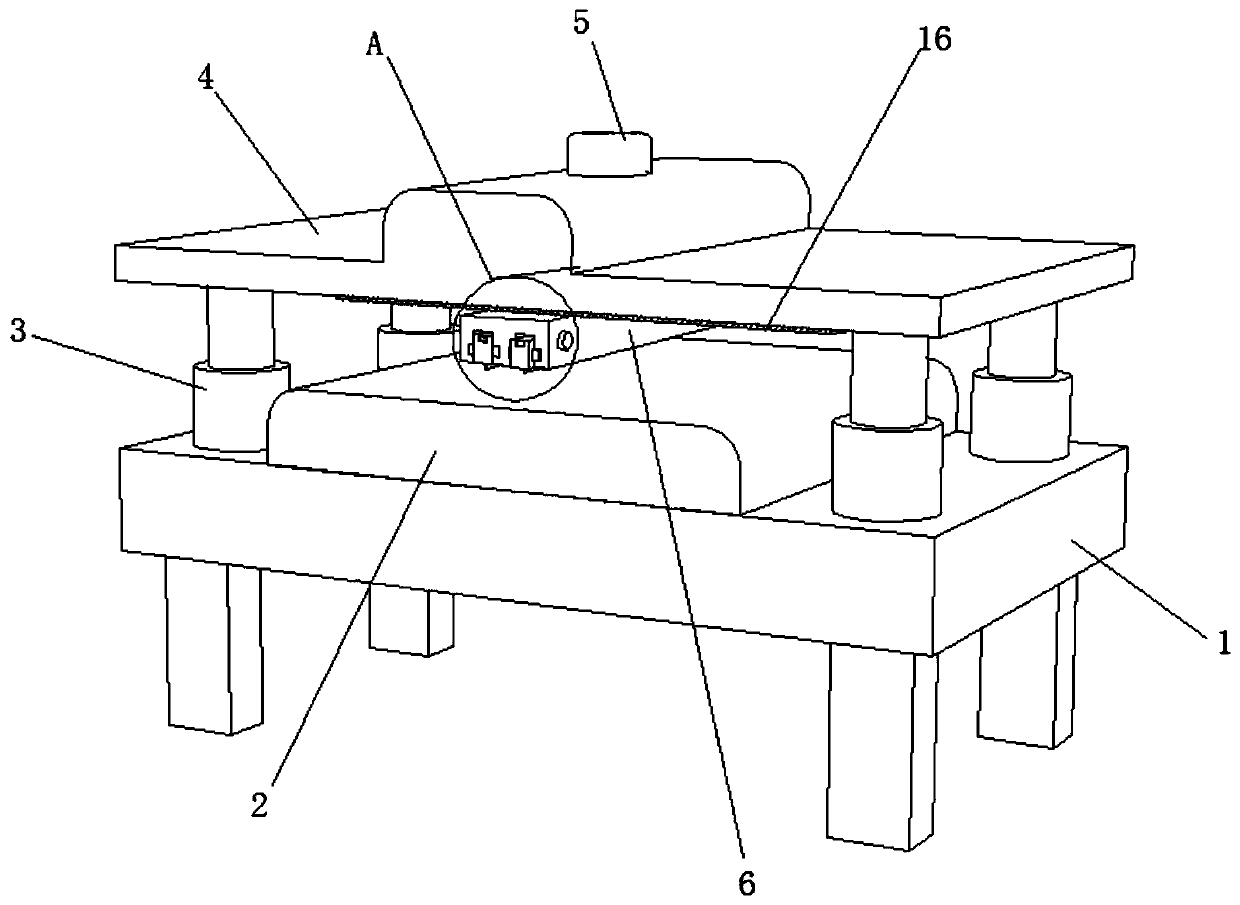
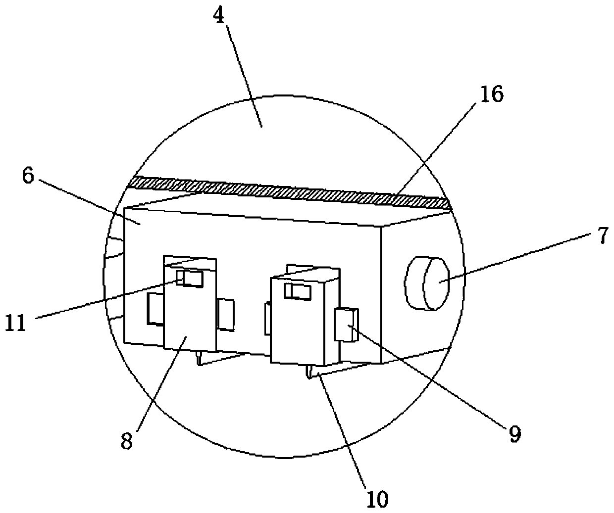
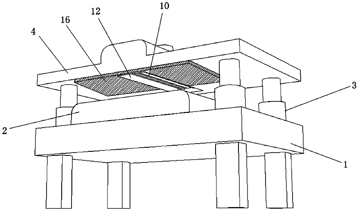
[0032] see figure 1 and image 3 , a tape punching device for copper foil tape production, including a punching table 2 fixedly connected to the upper end of the workbench 1, the upper side of the punching table 2 is provided with a lift cover 4, and the lift cover 4 and the workbench 1 There are many pairs of electric telescopic rods 3 fixedly connected, and a through hole is drilled from top to bottom at the center of the lifting cover plate 4, please refer to figure 1 and figure 2 , a cylinder 5 is connected to the center of the upper end face of the lifting cover plate 4, and the power output end of the cylinder 5 passes through the through hole and is fixedly connected to the lifting block 6, please refer to image 3 , the lower end of the lifting cover plate 4 is excavated with a receiving groove 12 matching the lifting block 6, please refer to Figure 4 , the lower end of the lifting block 6 is dug with a protective groove 14, and the inner side wall of the protecti...

Embodiment 2

[0039] see image 3 , the lower end surface of the lifting cover 4 is glued with a soft pad 16, and the soft pad 16 matches the upper end surface of the punching table 2. When idle, the lifting cover 4 is covered on the upper side of the punching table 2, and the soft pad 16 is directly connected to the punching table 2. The upper end surfaces of the table 2 are in contact with each other, which can play a certain buffering effect, and the sealing effect is better, so as to better protect the cutter head 10 from being corroded by the external environment.


PUM


Abstract

The invention discloses an adhesive tape blanking device for copper foil adhesive tape production, and belongs to the field of blanking devices. The adhesive tape blanking device for copper foil adhesive tape production comprises a blanking table fixedly connected to the upper end of a worktable; a lifting cover plate is arranged on the upper side of the blanking table; multiple pairs of electricextension rods are fixedly connected between the lifting cover plate and the worktable; a through hole is drilled in the center of the lifting cover plate from top to bottom; a cylinder is connected to the center of the upper end surface of the lifting cover plate; a power output end of the cylinder penetrates through the through hole, and is fixedly connected with a lifting block; a storage groove matched with the lifting block is drilled in the lower end of the lifting cover plate; a protective groove is drilled in the lower end of the lifting block; a pair of chutes is drilled in the innerside wall of the protective groove; and a tool bit module is arranged in the protective groove. According to the adhesive tape blanking device for copper foil adhesive tape production, the tool bit module can be conveniently and flexibly replaced, the tool bit can be reversely inserted in the protective groove in an idle state to be protected from being rusted by the external environment, and higher safety achieve is achieved.

Description

technical field [0001] The invention relates to the field of punching devices, in particular to a tape punching device for copper foil tape production. Background technique [0002] Copper foil tape is a kind of metal tape. It is mainly used in electromagnetic shielding. It is divided into two types: electrical signal shielding and magnetic signal shielding. Electrical signal shielding mainly relies on the excellent electrical conductivity of copper itself, while magnetic shielding requires copper foil tape. Surface conductive material "nickel" is used to achieve the effect of magnetic shielding, so it is widely used in mobile phones, notebook computers and other digital products. [0003] Punching is a stamping process that uses a die to separate part of the material or process part from another part of the material, process (process) part or waste. Blanking is a general term for separation processes such as shearing, blanking, punching, punching, notching, sectioning, chi...

Claims


Application Information

Patent Timeline
Patent Type & Authority Applications(China)
IPC IPC(8): B26F1/40B26D7/22B26D7/26B26D7/00
CPCB26D7/00B26D7/22B26D7/2614B26D2007/2607B26F1/40
Inventor 刘超
Owner 湖北富和冠电子材料有限公司
Why Eureka
Eureka Blog
Learn More