An optical instrument for lens polishing

An optical instrument and lens technology, applied in the field of glasses, can solve the problems of low grinding efficiency, damage to the lens surface, and poor grinding accuracy, and achieve the effects of high grinding efficiency, guaranteed clarity, and guaranteed grinding accuracy

Active Publication Date: 2020-08-04
江西弘耀光学水晶有限公司
View PDF7 Cites 0 Cited by
  • Summary
  • Abstract
  • Description
  • Claims
  • Application Information

AI Technical Summary

Problems solved by technology

[0002] The lens is a transparent material with one or more curved surfaces made of optical materials such as glass or resin. After being polished, it is often assembled with the spectacle frame to form glasses, which is used to correct the user's vision and obtain a clear vision. Among them, the lens is polished and shaped The process is particularly important. In the existing lens grinding, the lens is usually manually held, and the edge of the lens is in contact with the rotating grinding wheel to polish the lens. During the grinding process, the polisher needs to customize the shape of the lens according to the size of the frame or rely on experience. And the size, need to stop after polishing once, assemble and compare the lens with the frame, and then continue to polish and debug until the two are perfectly assembled. During this process, when the lens is held by hand, the surface of the lens will be damaged, and the adjustment and shutdown will be repeated. Resulting in low grinding efficiency and poor grinding accuracy

Method used


Image

  • An optical instrument for lens polishing
  • An optical instrument for lens polishing
  • An optical instrument for lens polishing

Examples


Embodiment Construction

[0019] Combine below Figure 1-Figure 4 The present invention is described in detail, and for convenience of description, the orientations mentioned below are now stipulated as follows: figure 1 The up, down, left, right, front and back directions of the projection relationship itself are the same.

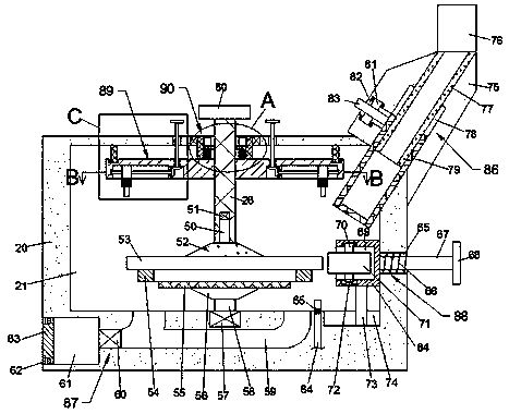
[0020] The present invention relates to an optical instrument used for lens grinding, mainly used for lens grinding work, the present invention will be further described below in conjunction with the accompanying drawings of the present invention:

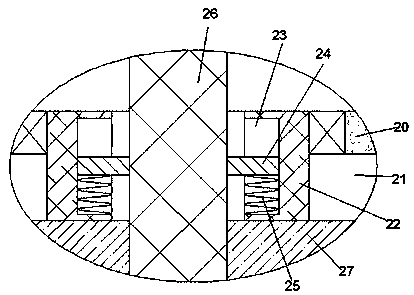
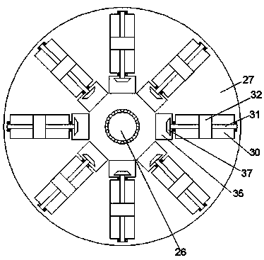
[0021] An optical instrument for lens grinding according to the present invention includes a body 20, a grinding cavity 21 is arranged in the body 20, a placing disc 55 is arranged in rotation in the grinding cavity 21, and the placing disc 55 is placed There is a picture frame 54, on which a lens 53 is placed, the upper side of the lens 53 is provided with a liftable stretching rod 26 through a telescopic device 90, the outer periphe...


PUM


Abstract

The invention discloses an optical instrument for lens grinding, which comprises a body, a grinding cavity is arranged in the body, a placing plate is rotated in the grinding cavity, a picture frame is placed on the placing plate, and a picture frame is placed on the picture frame. A lens is placed, and the upper side of the lens is provided with a liftable stretching rod through a telescopic device. The outer periphery of the stretching rod is a spline structure, and a suction cup is installed at the lower end of the stretching rod. , use the laser to draw the grinding track on the lens to provide the shape accuracy during grinding, and grind the lens through the mutual cooperation of the automatic uniform rotation of the lens and the horizontal movement of the automatically rotating grinding wheel. During the grinding process, it can be observed through the optical device The grinding situation ensures the grinding accuracy. In addition, the glass or resin slag generated during grinding is collected downward through the recovery device to ensure the clarity of observation, and the slag will not fly and affect the grinding. It is formed once and the grinding efficiency is high.

Description

technical field [0001] The invention relates to the technical field of glasses, in particular to an optical instrument for polishing lenses. Background technique [0002] The lens is a transparent material with one or more curved surfaces made of optical materials such as glass or resin. After being polished, it is often assembled with the spectacle frame to form glasses, which is used to correct the user's vision and obtain a clear vision. Among them, the lens is polished and shaped The process is particularly important. In the existing lens grinding, the lens is usually manually held, and the edge of the lens is in contact with the rotating grinding wheel to polish the lens. During the grinding process, the polisher needs to customize the shape of the lens according to the size of the frame or rely on experience. And the size, need to stop after polishing once, assemble and compare the lens with the frame, and then continue to polish and debug until the two are perfectly a...

Claims


Application Information

Patent Timeline
Patent Type & Authority Patents(China)
IPC IPC(8): B24B9/14B24B55/12B24B55/00
CPCB24B9/14B24B9/146B24B55/00B24B55/12
Inventor 胡江龙
Owner 江西弘耀光学水晶有限公司
Why Eureka
Try Eureka