
Cord-driven two-degree-of-freedom electromagnetic energy harvester

A degree of freedom, electromagnetic technology, applied in electrical components, electromechanical devices, electric components, etc., can solve the problems of reducing the output power, large energy loss, and low output power of the energy harvester, so as to alleviate the resonance frequency mismatch and reduce the Energy loss, effects for a wide range of applications

Active Publication Date: 2019-12-31
XIDIAN UNIV
View PDF4 Cites 2 Cited by
  • Summary
  • Abstract
  • Description
  • Claims
  • Application Information

AI Technical Summary

Problems solved by technology

The problems of this energy harvester include: (1) The rotor has a small torsion angle and low output power; (2) It needs to be placed vertically and can only work under the excitation of the vertical direction; (3) The rotor and cylinder There is friction and collision between the walls, and the energy loss is large
The problems of the energy harvester include: (1) The single-degree-of-freedom characteristic of the energy harvester leads to a narrow operating frequency band; (2) It can only work under the excitation of the vertical direction, which limits the work of the energy harvester environment; (3) The collision and friction between the rotor and the cylinder wall will cause a large energy loss and reduce the output power of the energy harvester

Method used


Image

  • Cord-driven two-degree-of-freedom electromagnetic energy harvester
  • Cord-driven two-degree-of-freedom electromagnetic energy harvester
  • Cord-driven two-degree-of-freedom electromagnetic energy harvester

Examples


Embodiment Construction

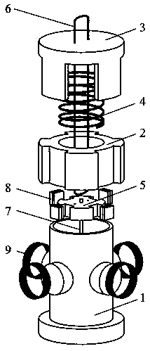
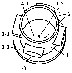
[0031] like figure 1 , figure 2 , Figure 7 A two-degree-of-freedom electromagnetic energy harvester driven by a wire is shown, at least including a base 1, a support cylinder 2, a top cover 3, a spring 4, a rotor 5, a wire 6, a guide rod 7, four magnets 8, four a coil 9; the support cylinder 2 includes a large counterbore 2-1, a small counterbore 2-2 and four support cylinder grooves 2-3; the large counterbore 2-1 is located on the bottom surface of the support cylinder 2, and The support cylinder 2 is coaxial; the small counterbore 2-2 is located on the top surface of the support cylinder 2 and is coaxial with the support cylinder 2; the four support cylinder grooves 2-3 are evenly distributed on the side of the support cylinder 2; The lower end of the spring 4 is fixedly connected to the small counterbore 2-2 of the support column 2, and the large counterbore 2-1 of the support column 2 is overlaid on the cylinder 1-2 of the base 1, and the spring 4 is connected to the b...


PUM


Abstract

The invention relates to a cord-driven two-degree-of-freedom electromagnetic energy harvester and belongs to the technical field of new energy and micro power generation. The energy harvester is characterized by at least comprising a base, a supporting cylinder, a top cover, a spring, a rotor, a cord, a guide rod, four magnets and four coils, wherein the supporting cylinder comprises a large counter bore, a small counter bore and four supporting cylinder grooves, the large counter bore is located at a bottom face of the supporting cylinder and is coaxial with the supporting cylinder, the smallcounter bore is formed on a top surface of the supporting cylinder and is coaxial with the supporting cylinder, the four supporting cylinder grooves are evenly distributed on a side face of the supporting cylinder, a lower end of the spring is fixedly connected with the small counter bore of the supporting cylinder, and the large counter bore of the supporting cylinder is sleeved on a cylinder ofthe base to connect the spring with the base. The energy harvester is advantaged in that the rotor is driven by a code, external low-frequency vibration, linear reciprocating motion, pressing motionand other excitations can be converted into high-speed rotating motion of the rotor, and the motor has advantages of wide working frequency band, large output power, wide application range and the like.

Description

technical field [0001] The invention belongs to the technical field of power generation, and in particular relates to a two-degree-of-freedom electromagnetic energy harvester driven by wires, which is suitable for portable electronic devices, wearable systems, micro sensors, etc. that need to capture the surrounding ultra-low frequency mechanical energy for energy supplementation low power devices. Background technique [0002] The rapid development of modern microelectronics and micro-manufacturing technology has led to the emergence of various low-power miniature devices. Although traditional electrochemical batteries can drive these tiny devices to work normally, many defects of batteries, such as limited energy storage, harmful chemical components, and high cost of regular replacement, force people to seek new energy technologies. The ideal power supply scheme is to convert the renewable energy present in the environment into electrical energy that can be used by low-po...

Claims


Application Information

Patent Timeline
Patent Type & Authority Applications(China)
IPC IPC(8): H02K7/18H02K7/06
CPCH02K7/06H02K7/1807
Inventor 樊康旗谭钦雪任获荣蔡美玲
Owner XIDIAN UNIV
Learn More