A two-degree-of-freedom piezoelectric-electromagnetic hybrid energy harvester

An energy harvester and hybrid technology, applied in piezoelectric effect/electrostrictive or magnetostrictive motors, generators/motors, electrical components, etc., which can solve the problem of low output power and inability to efficiently collect low-frequency vibration energy, etc. problem, to achieve the effect of large output power, simple structure and easy implementation

Active Publication Date: 2019-05-07
XIDIAN UNIV
View PDF5 Cites 0 Cited by
  • Summary
  • Abstract
  • Description
  • Claims
  • Application Information

AI Technical Summary

Problems solved by technology

[0006] The purpose of the present invention is to overcome the deficiencies of the above-mentioned prior art, and provide a two-degree-of-freedom piezoelectric-electromagnetic hybrid energy harvester with simple and compact structure, low cost of use, and a wide range of applications, so as to overcome the existing piezoelectric, electromagnetic The output power of piezoelectric and electromagnetic hybrid energy harvesters is low, and they cannot efficiently collect low-frequency vibration energy.

Method used


Image

  • A two-degree-of-freedom piezoelectric-electromagnetic hybrid energy harvester
  • A two-degree-of-freedom piezoelectric-electromagnetic hybrid energy harvester
  • A two-degree-of-freedom piezoelectric-electromagnetic hybrid energy harvester

Examples


Embodiment 1

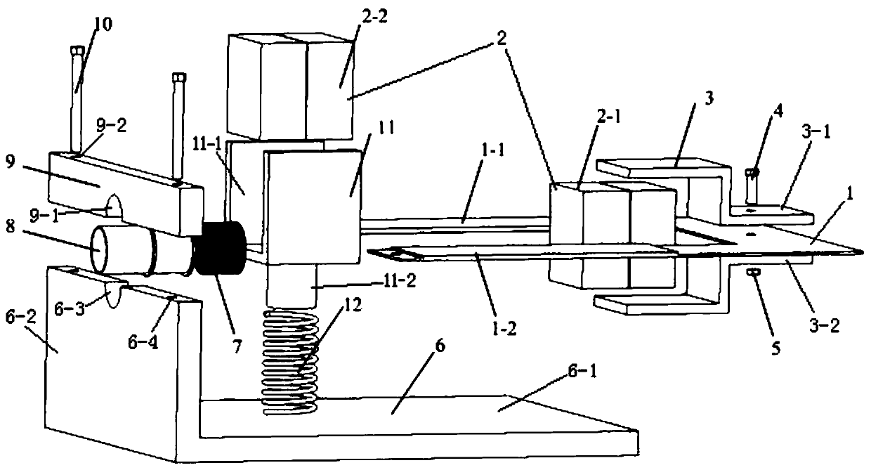
[0030] see figure 1, the present invention provides a two-degree-of-freedom piezoelectric-electromagnetic hybrid energy harvester, which at least includes a U-shaped cantilever beam 1, a magnet 2, a detachable clamp 3, a frame 6, a coil 7, a cylinder 8, and a fixed clamp 11 , spring 12; The magnet 2 includes a first magnet 2-1 and a second magnet 2-2; The frame 6 includes a bottom plate 6-1 and a vertical wall 6-2 that are firmly connected together; The U-shaped The cantilever beam 1 is composed of a first piezoelectric cantilever beam 1-1 and a second piezoelectric cantilever beam 1-2. The open end of the U-shaped cantilever beam 1 is fixedly connected to the vertical wall 6-2 of the frame 6. The piezoelectric cantilever beam 1-1 and the second piezoelectric cantilever beam 1-2 are parallel in the horizontal plane, and the free end of the U-shaped cantilever beam 1 is fixedly connected to the first magnet 2-1 through a detachable clamp 3. A magnet 2-1 is located between the ...

Embodiment 2

[0032] On the basis of Embodiment 1, the open end of the U-shaped cantilever beam 1 is fixedly connected to the vertical wall 6 - 2 of the frame 6 through the cover plate 9 and the screw 10 .

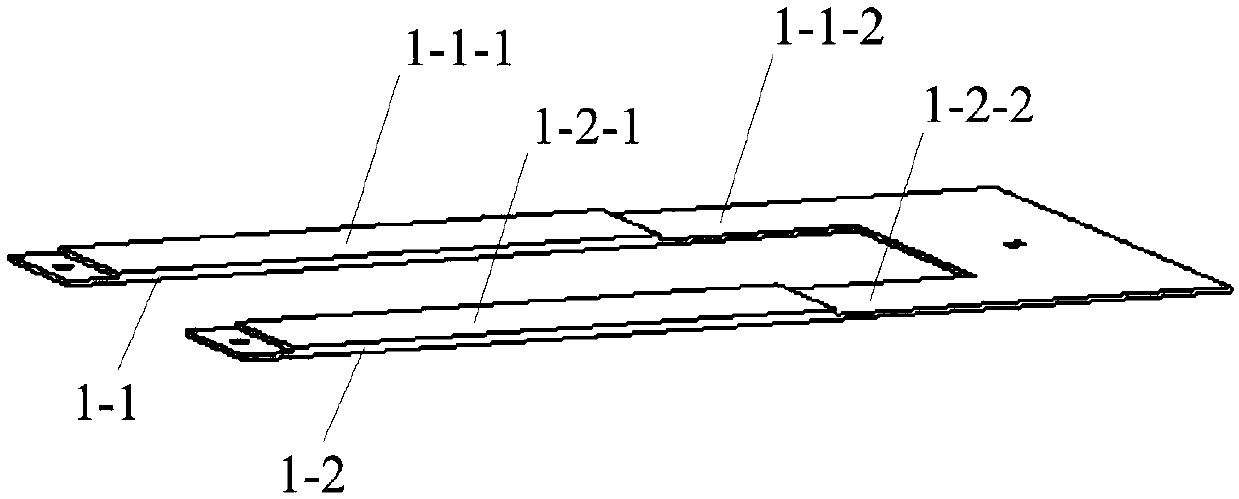
[0033] like figure 2 As shown, the first piezoelectric cantilever 1-1 includes a first piezoelectric element 1-1-1 and a first rectangular piezoelectric metal beam 1-1-2; the second piezoelectric cantilever 1- 2 includes a second piezoelectric element 1-2-1 and a second rectangular piezoelectric metal beam 1-2-2; the first piezoelectric element 1-1-1 is fixed to the first rectangular piezoelectric On the metal beam 1-1-2, the second piezoelectric element 1-2-1 is fixed on the second rectangular piezoelectric metal beam 1-2-2 through conductive glue; the first piezoelectric element 1-1 -1 is polarized along the thickness direction of the first rectangular piezoelectric metal beam 1-1-2, and the electrodes of the first piezoelectric element 1-1-1 are connected in series or in parallel; ...


PUM


Abstract

The invention belongs to the technical field of renewable energy and miniature power generation, and particularly relates to a two-degree-of-freedom piezoelectric electromagnetic hybrid energy harvester. The energy harvester at least comprises a U-shaped cantilever beam, magnets, a detachable fixture, a frame, a coil, a cylinder, a fixed fixture and a spring; the U-shaped cantilever beam is composed of a first piezoelectric cantilever beam and a second piezoelectric cantilever beam, the opening end of the U-shaped cantilever beam is fixedly connected with the vertical wall of the frame, and the free end of the U-shaped cantilever beam is fixedly connected with the first magnet; a piezoelectric energy harvester body is formed by the U-shaped cantilever beam, the detachable fixture and the first magnet; the coil is formed by winding enameled wires along the right half part of the outer wall of the cylinder; the cylinder is fixedly connected with the vertical wall of the frame; the fixedfixture is used for clamping the second magnet; the homopolar parts of the second magnet and the first magnet are opposite to each other; an electromagnetic energy harvester body is formed by the fixed fixture, the second magnet, the spring and the coil. The two-degree-of-freedom piezoelectric electromagnetic hybrid energy harvester has the advantages of being simple and compact in structure, highin energy collection efficiency and low in use cost.

Description

technical field [0001] The invention belongs to the technical field of renewable energy and micro power generation, and in particular relates to a hybrid energy harvester based on piezoelectric effect and electromagnetic induction effect, which is suitable for micro sensors, micro actuators, wearable electronic devices, etc. A low-power device that captures energy for energy supplementation. Background technique [0002] The continuous advancement of technologies such as microelectronics, micromechanics, and micromanufacturing has promoted the continuous emergence of various low-power devices such as microsensors, microactuators, microsignal transmitters, and wearable electronic devices. The power consumption of these devices is small, typically in the milliwatt range. Currently, these low-power devices are powered primarily by electrochemical batteries. The battery has limited energy storage and short service life, and needs to be charged or replaced regularly, which brin...

Claims


Application Information

Patent Timeline
Patent Type & Authority Patents(China)
IPC IPC(8): H02N2/18
CPCH02N2/188
Inventor 樊康旗任获荣朱应敏王卫东张大兴
Owner XIDIAN UNIV
Why Eureka
Try Eureka