
Display panel and display device

A display panel and display surface technology, which is applied in the direction of instruments, nonlinear optics, optics, etc., can solve the problem of low light quantity, achieve the effect of increasing transmittance, improving the received light quantity, and uniform mechanical strength

Inactive Publication Date: 2019-12-27
WUHAN TIANMA MICRO ELECTRONICS CO LTD
View PDF7 Cites 19 Cited by
  • Summary
  • Abstract
  • Description
  • Claims
  • Application Information

AI Technical Summary

Problems solved by technology

[0003] In view of this, an embodiment of the present invention provides a display panel and a display device to solve the problem in the prior art that the optical module under the screen receives less light

Method used


Image

  • Display panel and display device
  • Display panel and display device
  • Display panel and display device

Examples


Embodiment Construction

[0022] In order to better understand the technical solutions of the present invention, the embodiments of the present invention will be described in detail below in conjunction with the accompanying drawings.

[0023] It should be clear that the described embodiments are only some of the embodiments of the present invention, not all of them. Based on the embodiments of the present invention, all other embodiments obtained by persons of ordinary skill in the art without creative efforts fall within the protection scope of the present invention.

[0024] Terms used in the embodiments of the present invention are only for the purpose of describing specific embodiments, and are not intended to limit the present invention. As used in the embodiments of the present invention and the appended claims, the singular forms "a", "said" and "the" are also intended to include the plural forms unless the context clearly indicates otherwise.

[0025] It should be understood that the term "an...


PUM


Abstract

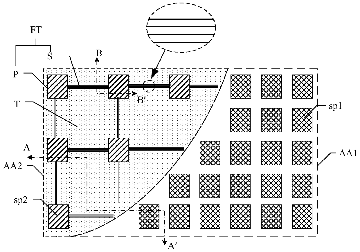
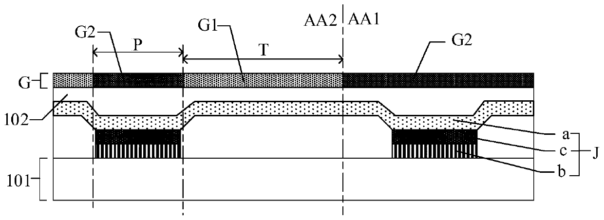
The invention provides a display panel and a display device. The display panel comprises a first display area, a virtual hole area and a polarization structure, wherein the pixel density of the virtual hole area is smaller than that of the first display area, the virtual hole area comprises a plurality of light transmission areas and a plurality of non-light transmission areas, and the non-light transmission areas comprise pixel areas and routing areas; and the polarization structure is positioned on one side of the display surface of the display panel and comprises a first polarization part and a second polarization part, the light transmittance of the first polarization part is larger than that of the second polarization part, each light transmission area comprises a first light transmission part, and each pixel area comprises a second light transmission part. According to the display panel, the transmittance of the light transmission areas can be increased, and the received light quantity of an optical module under a screen is increased.

Description

【Technical field】 [0001] The present invention relates to the field of display technology, in particular to a display panel and a display device. 【Background technique】 [0002] For electronic products, the setting of optical modules such as front cameras will inevitably occupy a certain amount of space, thereby affecting the screen-to-body ratio. In order to achieve a true full screen, researchers consider the implementation of optical modules under the screen. Set the optical module such as the camera under the light-emitting device of the display panel, that is, set the optical module in the display area, and the position of the optical module can be displayed normally. When the optical module needs to be used, the light penetrates the display panel to reach Optical modules are ultimately utilized by optical modules. The light-emitting devices occupy most of the space in the display area, and the area of ​​the light-transmitting area in the display area is small, so the...

Claims


Application Information

Patent Timeline
Patent Type & Authority Applications(China)
IPC IPC(8): G02F1/1335
CPCG02F1/133528
Inventor 李音张洁
Owner WUHAN TIANMA MICRO ELECTRONICS CO LTD
Learn More