
Air source heat pump electric thermal storage system and control method

An air source heat pump and electric heat storage technology, which is applied in heating systems, heating methods, space heating and ventilation, etc., can solve the problems of complex systems, huge hot water storage tanks, and reduced efficiency of heat storage heat pumps.

Inactive Publication Date: 2019-12-27
邬志军
View PDF3 Cites 2 Cited by
  • Summary
  • Abstract
  • Description
  • Claims
  • Application Information

AI Technical Summary

Problems solved by technology

[0006] The purpose of the present invention is to provide an air source heat pump electric heat storage system and its control method, which solves the problem that the existing air source heat pump combined with electric heat storage system cannot use water heat storage or heat storage due to the low temperature of the heat pump outlet water. The hot water tank is too large, the efficiency of the heat storage heat pump is reduced during heating, the system is complicated after the electric boiler and the heat storage device are separated, and the floor area is large, etc., and the equipment matching principle and guarantee for the high temperature air source heat pump heat storage system are provided The control method under the operating principle of the lowest heating quality and operating cost at the end load

Method used


Image

  • Air source heat pump electric thermal storage system and control method
  • Air source heat pump electric thermal storage system and control method

Examples


Embodiment Construction

[0056] In the following, the present invention will be specifically described through exemplary embodiments. It should be understood, however, that elements, structures and characteristics of one embodiment may be beneficially incorporated in other embodiments without further recitation.

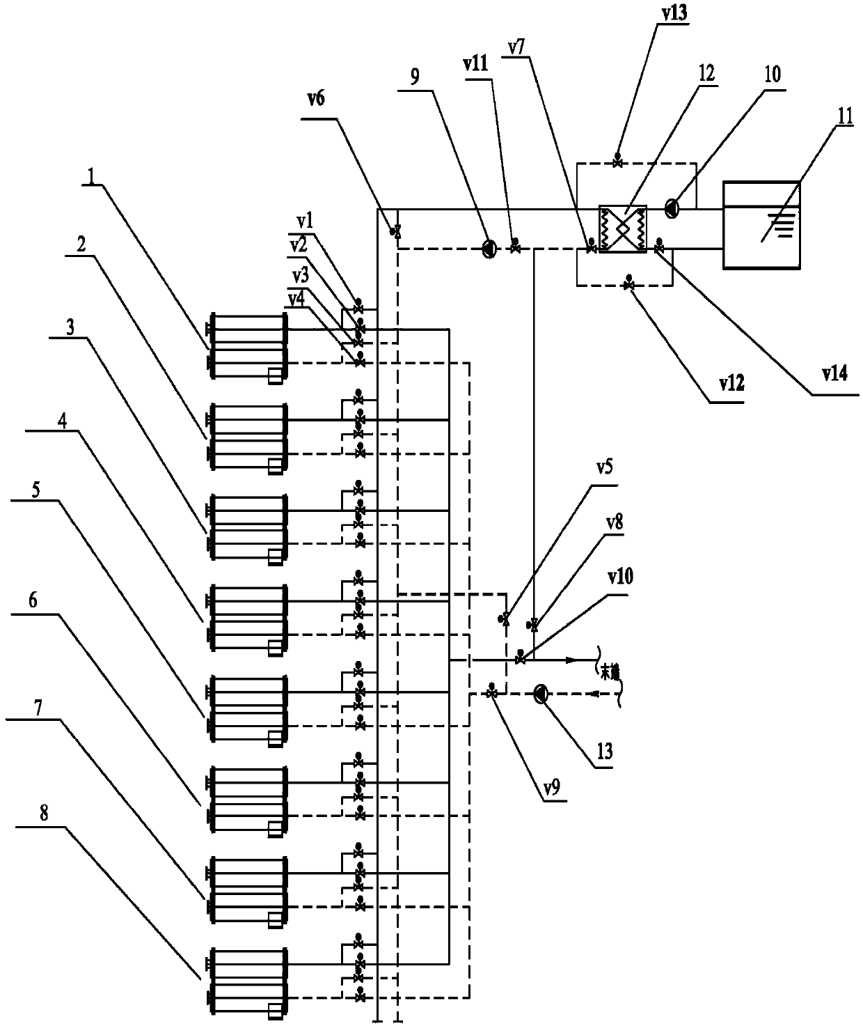
[0057] Such as figure 1 As shown, the air source heat pump electric heat storage system according to an embodiment of the present invention includes:

[0058] Eight heat pumps, namely the first heat pump 1, the second heat pump 2, the third heat pump 3, the fourth heat pump 4, the fifth heat pump 5, the sixth heat pump 6, the seventh heat pump 7, and the eighth heat pump 8, each heat pump is set 4 electric valves, specifically setting electric valves v1 and v2 at the water outlet of each heat pump, and setting electric valves v3 and v4 at the water inlet of each heat pump (only the four electric valves on the first heat pump 1 are marked in the figure The positions of the electric valves v...


PUM


Abstract

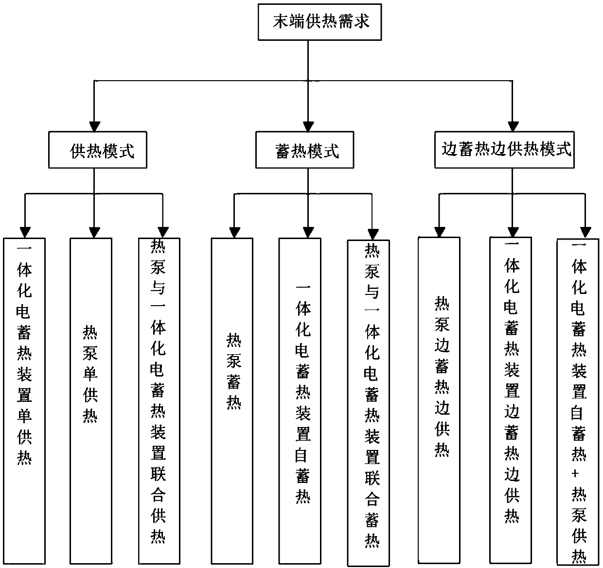
The invention discloses an air source heat pump electric thermal storage system and a control method. The system comprises at least one air source heat pump, at least one integrated electric thermal storage device, a plate type heat exchanger, a primary side water pump, a secondary side water pump, a circulating pipeline, cables and a control system, wherein the primary side water pump and the secondary side water pump are distributed on the two sides of the plate type heat exchanger, the circulating pipeline interconnects water flow of equipment and supplies heat to a terminal, the cables areused for supplying power to the equipment in the system, and the control system controls the operational process of the whole system; the integrated electric thermal storage devices integrate an electric heating device and a thermal storage device into integrated equipment, at least one of the air source heat pumps is a high-temperature air source heat pump, and the control system controls the air source heat pump electric thermal storage system to flexibly switch among a plurality of different operational modes. The system has the advantages that through the integrated electric thermal storage devices, the configuration number of the heat pumps is decreased, the system is simplified, the initial investment of the equipment is lowered, the reliability of the system is enhanced, in addition, clean energy is reasonably utilized, the occupied area of the system is small, the system efficiency is high, furthermore, the off-peak electricity can be fully utilized, and the operation cost islow.

Description

technical field [0001] The invention relates to the technical field of heating, in particular to an air source heat pump electric heat storage system and a control method. Background technique [0002] Air source heat pump heating and thermal storage heating are currently the two most widely used electric heating methods. The cost of air source heat pumps is high, and it takes up a large outdoor space, causing noise pollution, and when the ambient temperature is low, the heat efficiency of air source heat pumps is low, or it cannot operate due to frosting on the outdoor evaporator. These defects affect the air quality. Promotion of source heat pumps. Electric thermal storage heating is not affected by the ambient temperature, but because the heat stored during the off-peak period needs to be used throughout the day, the electric power load is relatively large, and the current low-valley electricity prices in various provinces and cities are not cheap enough, so the heating ...

Claims


Application Information

Patent Timeline
IPC IPC(8): F24D15/04F24D15/02F24D19/10
CPCF24D15/02F24D15/04F24D19/1006F24D2200/32
Inventor 邬志军
Owner 邬志军
Learn More