
Long-distance passive wireless magnetic field quantity sensing system

A passive wireless, sensing system technology, applied in the field of electronic communication technology and sensors, can solve the problems of high cost, high power consumption, increased cost, etc., and achieve the effect of convenient maintenance and maintenance, low maintenance cost, and low total cost.

Active Publication Date: 2019-12-24
UNIV OF ELECTRONIC SCI & TECH OF CHINA
View PDF6 Cites 4 Cited by
  • Summary
  • Abstract
  • Description
  • Claims
  • Application Information

AI Technical Summary

Problems solved by technology

The main shortcomings of the existing magnetic field sensing technology are: no introduction of RFID technology, no long-distance wireless transmission of magnetic field parameters
Moreover, the existing magnetic field sensing devices generally have high power consumption, and basically operate in active mode, which puts forward certain requirements for fixed power sources or portable batteries, and also increases the cost of regular maintenance, and in some Or in the special environment where the battery cannot be replaced, the existing technology has shown considerable limitations
Moreover, the existing magnetic field sensing equipment is relatively bulky and expensive, and it is not realistic for a large-area sensor network layout

Method used


Image

  • Long-distance passive wireless magnetic field quantity sensing system
  • Long-distance passive wireless magnetic field quantity sensing system
  • Long-distance passive wireless magnetic field quantity sensing system

Examples


Embodiment Construction

[0035] In order to facilitate those skilled in the art to understand the technical content of the present invention, the content of the present invention will be further explained below in conjunction with the accompanying drawings.

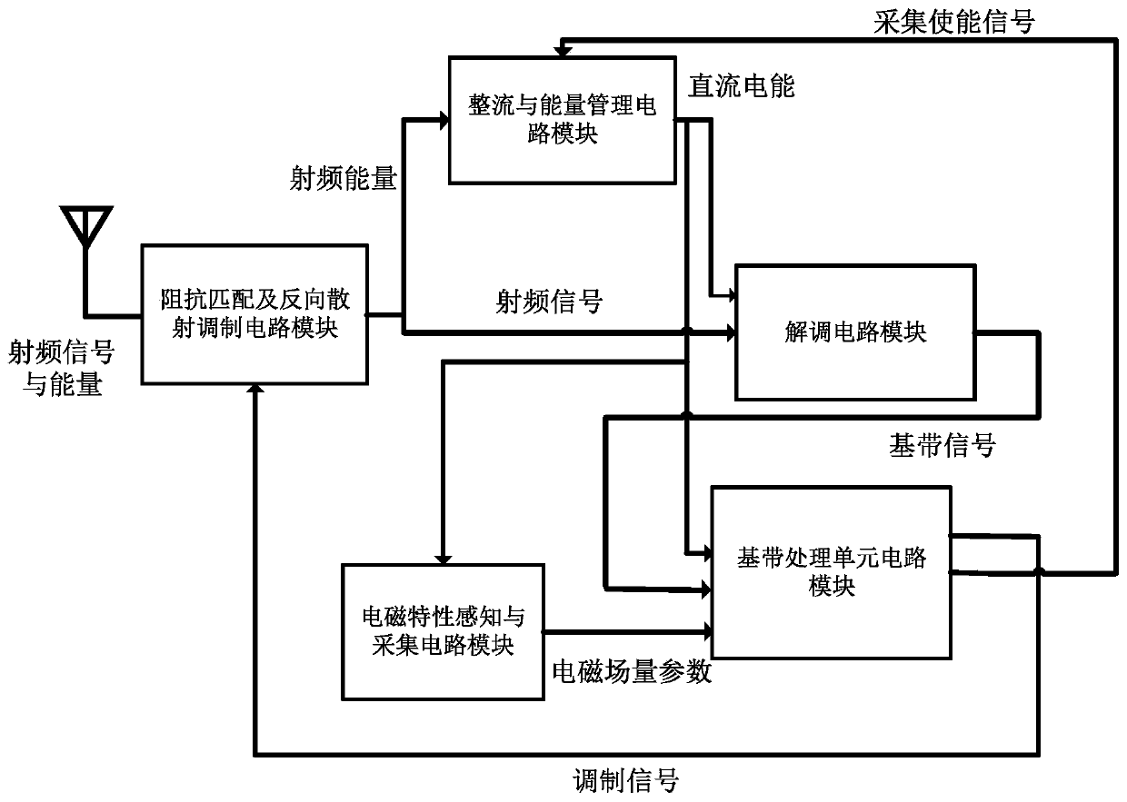
[0036] The invention adopts RFID technology, integrates the passive magnetic field sensor into the board-level passive electronic tag supporting the ISO / IEC 18000 protocol, and forms a long-distance passive wireless Magnetic field sensing system.

[0037] like figure 1 As shown, the long-distance passive wireless magnetic field sensing system of the present invention includes: a host computer, a reader and a magnetic field sensing tag; when the long-distance passive wireless magnetic field sensing system is working, it aims to realize the magnetic field to be measured The magnetic field strength parameters in the environment are intermittently collected and transmitted. The specific application scenarios are as follows figure 1shown.

[0038] ...


PUM


Abstract

The invention discloses a long-distance passive wireless magnetic field quantity sensing system and a method thereof. The method and the system are applied to the electronic communication technology and sensor technology field, and for the existing magnetic field quantity sensing, solve the problems that an existing magnetic field quantity sensing device is high in power consumption, large in size, high in cost, is difficult to maintain and the like are solved. The long-distance passive wireless magnetic field quantity sensing system is based on an RFID-based wireless communication technology,through a passive magnetic field sensor, and under the excitation of an excitation signal, outputs an output signal related to the surrounding magnetic field intensity, and adopts a rectification andenergy management circuit to convert the radio frequency energy sent by a reader-writer and received bya magnetic field quantity sensing label into the direct current electric energy and store, so that the energy for the magnetic field quantity sensing label during operation is provided. Compared with the prior art, the size of the magnetic field quantity sensing device is reduced, the productioncost is lower, the power consumption is smaller, the precision is high, and the remote wireless sensing can be achieved.

Description

technical field [0001] The invention belongs to the field of electronic communication technology and sensor technology, and in particular relates to an RFID radio frequency identification technology and a wireless sensor network technology. Background technique [0002] Radio Frequency Identification (RFID, Radio Frequency Identification) technology is a traditional wireless communication identification technology, which can realize non-line-of-sight communication, and is widely used in intelligent logistics, transportation, multi-target identification, azimuth tracking and other fields. The application of RFID technology in wireless sensor networks can combine the technical characteristics of RFID and wireless sensor networks. It can automatically identify the characteristics of targets through RFID radio frequency signals, and can simultaneously realize the functions of wireless sensor network sensing information and communication. [0003] RFID reader (abbreviation for Ra...

Claims


Application Information

Patent Timeline
IPC IPC(8): G06K7/10G01R33/06H04B5/00
CPCG06K7/10158G01R33/063H04B5/77Y02D30/70
Inventor 李镇兵李钢文光俊文玉梅胡伟
Owner UNIV OF ELECTRONIC SCI & TECH OF CHINA
Learn More