Anchorage device clamping piece production line
A production line and clip technology, applied in the direction of manufacturing tools, other manufacturing equipment/tools, etc., can solve the problems of manpower consumption and insufficient efficiency
- Summary
- Abstract
- Description
- Claims
- Application Information
AI Technical Summary
Problems solved by technology
Method used
Image


Examples
Embodiment 1
[0067] A kind of anchor clip production line of the present embodiment, such as figure 1 As shown, it includes a synchronous processing part 200, a tapping processing part 100, and a half-cutting processing part 300 connected sequentially through the feeding lifting device 4 and the conveyor belt; the tapping processing part 100 includes at least one clip tapping set along the conveyor belt Silk device 1, the synchronous processing part 200 includes at least one synchronous processing device 2 arranged along the conveyor belt, and the half-cutting processing part 300 includes at least one clip cutting device 3 arranged along the conveyor belt.
[0068] Synchronous processing section 200 comprises at least one synchronous processing device 2 arranged along the conveyor belt of feeding, the other side of synchronous processing device 2 is provided with the conveyor belt of feeding parallel to the conveyor belt of feeding, and the feeding end of the conveyor belt of feeding is pro...
Embodiment 2
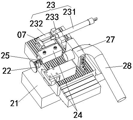
[0072] This embodiment is further optimized on the basis of the above-mentioned embodiment 1, such as figure 2 As shown, the synchronous processing device 2 includes a machine tool cross slide 21, the machine tool cross slide 21 is provided with a synchronous feeding device 23, and one side of the synchronous feeding device 23 is provided with a synchronous processing tool assembly 24; The end of the machine tool spindle on one side of the cross slide 21 of the machine tool is also equipped with a synchronous clamp 22 corresponding to the feeding end of the synchronous feeding device 23 , and a synchronous unloading device 25 is installed at one end of the synchronous clamp 22 .
[0073] The machine tool cross slide 21 adopts the existing machine tool slide. The machine tool cross slide 21 can move in the X direction and the Y direction in the horizontal plane. The X direction and the Y direction refer to two directions perpendicular to each other in the horizontal plane. Bot...
Embodiment 3
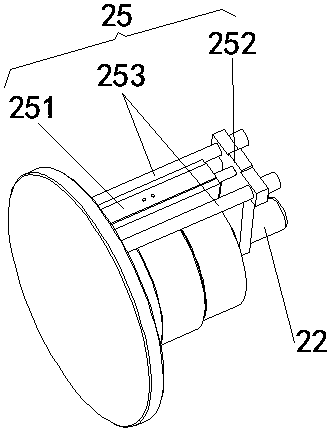
[0078] This embodiment is further optimized on the basis of embodiment 1 or 2, such as figure 2 and image 3 As shown, the synchronous unloading device 25 includes a synchronous unloading cylinder 251, a synchronous unloading push plate 252, and a synchronous unloading guide shaft 253, and the synchronous unloading cylinder 251 is fixedly installed on one side of the machine tool spindle. The push rod end of the unloading cylinder 251 is provided with a synchronous unloading push plate 252, and the synchronous unloading push plate 252 is provided with a perforation for the synchronous clamp 22 to pass through; the synchronous unloading guide shaft 253 is arranged in parallel on the synchronous unloading One side of the material cylinder 251 is also slidably connected with the synchronous unloading push plate 252.
[0079] The top of the synchronous unloading push plate 252 is welded or screwed to the synchronous unloading cylinder 251, and the bottom of the synchronous unloa...
PUM
 Abstract
Description
Claims
Application Information
 - R&D
- Intellectual Property
- Life Sciences
- Materials
- Tech Scout
- Unparalleled Data Quality
- Higher Quality Content
- 60% Fewer Hallucinations
Browse by: Latest US Patents, China's latest patents, Technical Efficacy Thesaurus, Application Domain, Technology Topic, Popular Technical Reports.
© 2025 PatSnap. All rights reserved.Legal|Privacy policy|Modern Slavery Act Transparency Statement|Sitemap|About US| Contact US: help@patsnap.com